
Model test of the mechanism underpinning water-and-mud inrush disasters during tunnel excavation in sandstone and slate interbedded Presinian strata
2022-11-30 09:51:20PengXUPengPENGRonghuaWEIZhiqiangZHANG
Peng XU ,Peng PENG ,Rong-hua WEI ,Zhi-qiang ZHANG?
1School of Civil Engineering,Southwest Jiaotong University,Chengdu 610031,China
2Key Laboratory of Transportation Tunnel Engineering,Ministry of Education,Southwest Jiaotong University,Chengdu 610031,China
Abstract: Water-and-mud inrush disasters have become a major challenge in underground engineering for the construction of tunnels in sandstone and slate interbedded Presinian strata.Disaster prediction and prevention rely in part on realistic modeling and observation of the disaster process,as well as the identification and examination of the underlying mechanisms.Based on the geological conditions and the historical records of the Xinping Tunnel on the China–Laos Railway,an engineering geological model of the water-and-mud inrush was established.A physical model test that accurately reproduced water-and-mud inrush during tunnel excavation in sandstone and slate interbedded strata was also carried out.Then,testing was conducted that examined the stress and strain,seepage pressure,and high-leakage flow of the surrounding rock.The results indicated that the water-and-mud inrush proceeded through three stages:seepage stage,high-leakage flow stage,and attenuation stage.In essence,the disaster was a catastrophic process,during which the water-resistant stratum was reduced to a critical safety thickness,a water-inrush channel formed,and the water-resistant stratum gradually failed under the influence of excavation unloading and in situ stress–seepage coupling.Parameters such as the stress and strain,seepage pressure,and flow of the surrounding rock had evident stage-related features during water-and-mud inrush,and their variation indicated the formation,development,and evolution of the disaster.As the tunnel face advanced,the trend of the stress–strain curve of the surrounding rock shifted from sluggish to rapid in its speed of increase.The characteristics of strain energy density revealed the erosion and weakening effect of groundwater on the surrounding rock.The seepage pressure and the thickness of the water-resistant stratum had a positive linear relationship,and the flow and thickness a negative linear relationship.There was a pivotal point at which the seepage pressure changed from high to low and the flow shifted from low to high.The thickness of the water-resistant stratum corresponding to the pivotal point was deemed the critical safety thickness.
Key words: Water-and-mud inrush;Sandstone and slate interbedded Presinian strata;Model test;Evolution law;Thickness of water-resistant stratum;Inducing mechanism
1 Introduction
With the introduction of the New Western Devel‐opment Strategy and Belt and Road Policy,the focus of China’s modern traffic engineering has gradually shifted to southwestern mountainous areas with extr?emely complex geological conditions.The sandstone and slate interbedded Presinian strata are extremely ancient and widely distributed in Southwest China.Many tunnels are being built in this region.Tunnel construction can result in water-and-mud inrush (Fan et al.,2018).Water-and-mud inrush disasters may cause significant scheduling delays in construction,economic loss,environmental damage,and casualties,all of which may lead to a project being abandoned or redesigned for a new location(Li LP et al.,2016).This has become a significant technological prob‐lem that has restricted tunnel construction in South‐west China (Ma et al.,2016;Wang et al.,2019).Therefore,for disaster control and prevention,it is of great scientific value and engineering significance to study the mechanisms inducing water-and-mud inrush events.
The inrush of water and mud during tunnel con‐struction can be attributed to a combination of factors,including the geological environment,construction dis‐turbances,and external loads,and occurs as a result of multiple stress mechanisms that result in seepage and damage.Theoretical and numerical simulations have been conducted by researchers worldwide to examine and mitigate the associated risks.Wu et al.(2017)selected a series of detection lines on a karst tunnel plane and obtained the corresponding velocity before water inrush in the tunnel and the subsequent pressure change curves,through numerical simulation.Zhao et al.(2018) also used numerical simulation to study the migration law of water inrush in three fault struc‐tures under different initial velocities and dynamic viscosities,and identified the causes of water inrush in fault tunnels.Yang WM et al.(2019a)analyzed the fluid-solid coupling between groundwater and the surrounding rock during tunnel excavation using the finite element method,and were able to summarize the pattern regularity of water inrush disasters.Yang et al.(2020a) developed a four-component numerical method to assess the effect of internal soil erosion on the stress state,initial soil density,and initial fine grain size based on continuous medium theory.Yang J et al.(2019b) investigated the effects of coupling between erosion and filtration by simulating a 1D internal ero‐sion test.Yang J et al.(2019a) used a finite element approach to numerically solve an elasto-plastic intrin‐sic model of a sandy-powdered soil mixture.This was used to monitor the effect of the evolution of porosity and fines content caused by internal erosion on the behaviour of the soil skeleton.Yang et al.(2020b)developed an elasto-plastic principal structure model of a sand-powder soil mixture.They analyzed the different damage modes of an embankment subjected to internal erosion caused by leakage at the base of the foundation under different boundary conditions according to a 3D finite element program.Wang et al.(2020)used the critical water-pressure theory of hydr?aulic fracturing and numerical simulations to study the process of collapse of surrounding rock under water pressure.Xue et al.(2021)discussed the causes of water-and-mud inrush in real-world scenarios,ana‐lyzed the evolution of water-and-mud inrush based on numerical simulation results,and suggested pre‐vention methods.Li et al.(2021) predicted the poten‐tial water-bearing area of the Jingzhai Tunnel (on the China–Laos Railway) using an electromagnetic method,and used numerical simulations to study the mechanism of water inrush and seepage transformation caused by excavation disturbances.Yang et al.(2022)investigated the effect of soil permeability on ground deformation by developing a novel coupled waterforce modelling approach based on mixture theory.
Numerical simulations need to limit the mechani‐cal parameters,flow patterns,and constitutive model‐ling.However,when water-and-mud inrush disasters occur in a real-world tunnel,the fields of stress,dis‐placement,and seepage in the surrounding rock vary broadly,which makes them hard to reproduce and cal‐culate in theoretical models.Physical models,however,can more accurately depict the spatial link between the geological body and the tunnel,as well as the cata‐strophic process of water-and-mud inrush,all of which are critical in predicting and preventing underground engineering disasters.Liang et al.(2016)analyzed the variations in stress,displacement,and water pres‐sure fields during tunnel excavation using water inrush modelling combined with engineering examples and related theories,and established risk criteria for water inrush.Li SC et al.(2016) monitored the vault dis‐placement,water pressure,and area of excavation dis‐turbance in a fault tunnel section using a physical model,and studied the mechanisms promoting water inrush in cross-fault tunnels.Jiang et al.(2017)used a series of geological disaster models involving water inrush to study the effects of the formation pressure,water pressure,and safety thickness of surrounding rock on water inrush disasters.Zhang et al.(2017)simulated the process of crack formation and hidden fault expansion as well as the evolution of a high water-pressure channel under a mining site.They found that the lagging water inrush was the result of fluidsolid coupling between cracks in the coal floor and tectonic rock zones.Yang WM et al.(2019b) devel‐oped a model for water inrush in tunnels with high ground stress and high-water pressure and found that the seepage and stress of the rock mass in the waterresistant layer changed significantly before the occur‐rence of water inrush.Li et al.(2019) monitored the displacement,stress,and seepage pressures of differ‐ent monitoring sections in a true triaxial geomechani‐cal model and obtained data from multiple physical responses involved in the surrounding rock failure and resultant water inrush.Yang WM et al.(2019c)analyzed a model of water inrush failure in an imper‐meable rock mass and estimated the variation in the displacement,stress,and seepage pressures of the sur‐rounding rock.Pan et al.(2019) studied the stability of surrounding rock in the process of karst tunnel excavation using a 3D model.Their study revealed the mechanism of water inrush and the variation of displacement and water pressure in the failure zone during construction.
Most studies have focused on the causes and pat‐terns of water-and-mud inrush disasters in karst tun‐nels and cross-fault tunnels,but there has been little research into the causes of these disasters in Presinian strata.Therefore,based on the recently completed Xin‐ping Tunnel built on the China–Laos Railway,we developed a model to reproduce the sandstone and slate interbedded Presinian strata and the entire pro‐cess of water-and-mud inrush,after developing a fluidsolid coupling with geologically similar materials.We analyzed the variation in the stress and seepage fields of the surrounding rock during tunnel excavation and provided an experimental basis for future research into the mechanisms underpinning water-and-mud inrush disasters.The knowledge gained will contribute to the prevention and mitigation of underground engi‐neering disasters.
2 Xinping Tunnel: description,geology,and disasters
2.1 Project overview
The Yuxi–Mohan (Yumo) Railway is an electri‐fied railway in Yunnan Province,China,which con‐nects Yuxi City with Mohan Port in Mengla County.It is an essential portion of the Trans-Asian Railway.The Yumo Railway is a hallmark project of China’s Belt and Road initiative,with a total length of 507 km and a maximum train speed of 160 km/h.A total of 93 tunnels were designed for the Yumo Railway,with a total length of 398 km.The Xinping Tunnel is the key control project for the entire line and had some of the most complex geological conditions.It was classified as a class I “high-risk” tunnel in which water-and-mud inrush disasters occur frequently dur‐ing construction.The Xinping Tunnel is located in Xin‐ping County,Yuxi City,Yunnan Province.Its entrance mileage marker is D1K46+290 and its exit mileage marker is D1K61+120.With a total length of 14.8 km,it is a single-entrance,double-line,super-long tun‐nel.Fig.1 depicts the topographic plan of the Xinping Tunnel.
The Xinping Tunnel was excavated using a threebench method with an excavation width of 12.8 m,a height of 11.6 m,and a cross-sectional area of 122 m2.A total of eight auxiliary channels were set,including six transverse galleries,one inclined shaft,and one parallel heading.Fig.2 is an illustration of a crosssection of the Xinping Tunnel.
2.2 Geological features of Presinian strata
The Xinping Tunnel is located in the middle of the Yunnan Plateau,northeast of the Ailao Mountain area,which belongs to a tectonically eroded lowmiddle mountain landform with complex topography,high mountains,and deep valleys.The Xinping Tun‐nel passes through Mopan Mountain,in the direction SW210°and at a maximum buried depth of 578 m.The average buried depth of the tunnel is around 270 m,while the height of groundwater head is between 40 and 60 m.A geological cross-section of the Xinping Tunnel is shown in Fig.2,and the strata are listed in Table 1.The Xinping Tunnel passes mainly through Tri‐assic and Presinian strata.Most of the tunnel is located in the sandstone and slate interbedded Presinian strata of the Heishantou Formation of the Kunyang Group(Pt1hs),which is also the segment with the highest fre‐quency of water-and-mud inrush disasters (D1K51+290 to D1K59+290 in Fig.3).The geological structure of the tunnel site was highly developed.The Xinping Tunnel lies between the Shiping–Jianshui fault zone and the Yangwu–Qinglongchang fault zone,parallel to the Yangwu–Qinglongchang fault zone.It passes through seven large and several small structures includ‐ing the Lukuishan syncline,Xinzhai anticline,Xinzhai reverse fault,Dakaimen–Xinzhai reverse fault,Xiemo reverse fault,Yangwu–Zhaomike reverse fault,and Abudu reverse fault.
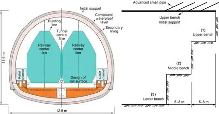
Fig.2 Diagram of a cross-section of the Xinping Tunnel and the three-bench method
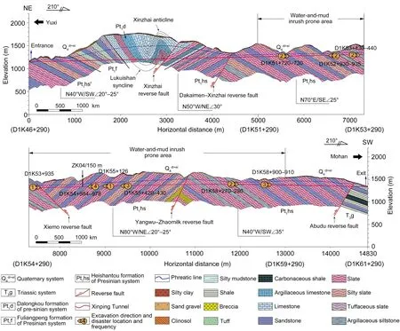
Fig.3 Longitudinal geological profile of the Xinping Tunnel
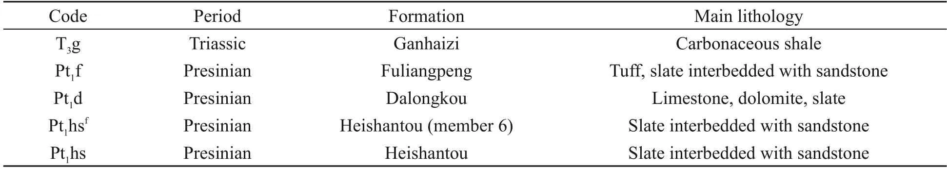
Table 1 Table of strata
The sandstone and slate interbedded Presinian strata are a kind of monoclinal,bedded structure com‐posed of groups of slate and sandstone strata with dip angles of 20°–35°.The thickness of a single slate stratum varies from thin to medium,ranging from 0.1 to 0.5 m.The thickness of a single sandstone stra‐tum varies from medium to thick,ranging from 0.5 to 1.0 m.There are three primary sets of joints growing in the strata,including J1 (N55°E/NW45°–60°),J2(N45°W/SW40°–50°),and J3 (N65°E/SE40°–45°).The joint spacing is typically 0.1–0.5 m,and the rock integrity coefficientKvis about 0.30.This suggests that there is a high degree of damage to the integrity of the formation,and the overall strength of the for‐mation is poor.The strata are controlled by weak struc‐tural planes and have poor stability.The sandstone and slate interbedded Presinian strata that were exposed during tunnel construction are shown in Fig.4.The general condition of the strata exposed by the tunnel face was characterized by interlayer wrinkling of the sandstone and slate interbedded strata,which had been affected by tectonic activity and structural planes.The strata were broken into fragments,showing the lay‐ered cataclastic structure.
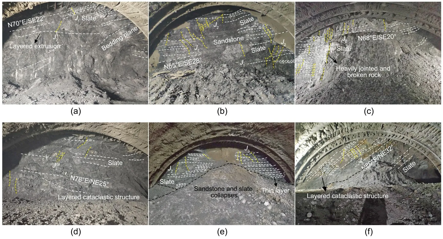
Fig.4 Geological survey of various tunnel faces: (a) D1K51+478;(b) D1K52+136;(c) D1K53+345;(d) D1K54+310;(e)D1K55+519.4;(f)D1K56+120
Fig.5 shows drilling cores of the sandstone and slate interbedded Presinian strata.The overlaying and underlying slate had weak integrity and self-stabilization capabilities based on the core characteristics.The sand‐stone core was highly fractured,revealing a fragmented structure(rock quality designation RQD=0),and there was little core recovery.Experimental measures of the physical and mechanical properties of the slate and sandstone in the Presinian strata are shown in Table 2(Choo and Ong,2020).
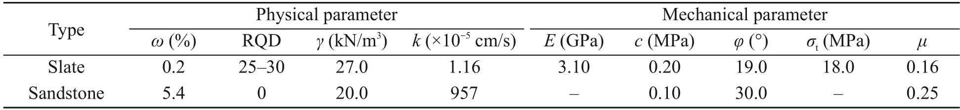
Table 2 Physical and mechanical parameters of slate and sandstone(Choo and Ong,2020)
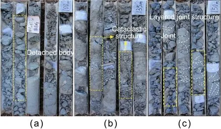
Fig.5 Core photographs of sandstone and slate interbedded Presinian strata:(a)94.8?97.7 m,overlying slate;(b)97.7?138.2 m,sandstone aquifer;(c)138.2?155.7 m,underlying slate
Generally,fractures close gradually as the depth increases in the distribution area of monocline,bed‐ded strata.As a result,as depth increases,the waterrichness of the strata declines,and the water-richness of deep interlayer fissures is often poor.However,the thick sandstone layer of the Presinian strata has abun‐dant voids and joints,good connectivity and permea‐bility,and the basic conditions to accommodate ground‐water.These features are conducive to groundwater flow and storage in the sandstone layer.Therefore,the sandstone strata could be considered the water-bearing stratum.The slate layer,which has closed fissures and low water permeability,provides favorable geologi‐cal conditions for groundwater collection and storage in the sandstone layer.Consequently,the slate strata were considered the water-resistant stratum.The mono‐clinic bedded water-bearing structure is formed by the combination of a sandstone water-bearing stratum and a slate water-resistant stratum,and has been the source of water-and-mud inrush disasters.In terms of permea‐bility of the entire structure,the permeability coeffi‐cient of the monoclinic bedded water-bearing structure is large in the direction parallel to the bedded plane,but small in the direction perpendicular to the bedded plane,which shows its anisotropic characteristics (Ong et al.,2022).Groundwater in monoclinal,bedded waterbearing structures is supplied mostly by atmospheric rainfall or surface water through the exposed part of the sandstone layer.
2.3 Cases of water-and-mud inrush disasters
According to on-site records,the Xinping Tunnel has had 41 water-and-mud inrush disasters since its construction,with a total mud inrush of 6.7×10⁴m3(including 20 in the main tunnel and 21 in auxiliary channels).From the D1K54+984 to the D1K54+978 mileage marker,there have been four successive water-and-mud inrush disasters,all of which were caused by the typical monoclinic,bedded water-bearing structure.The disaster scenes are shown in Fig.6.The sandstone water-bearing stratum had been exposed at the D1K54+982 mileage marker with a flow rate of 2.52 m3/h,and the dip of the strata in the section cor‐responded to the direction of tunnel excavation.
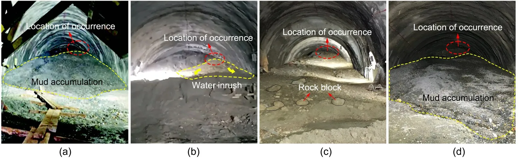
Fig.6 Scenes from the water-and-mud inrush disasters in the Xinping Tunnel with sandstone and slate interbedded strata:(a)Dec.8,2017;(b)Dec.12,2017;(c)Dec.22,2017;(d)Jan.19,2018
(a) The first water-and-mud inrush occurred at the D1K54+982 mileage marker on Dec.8,2017,with a mud inrush volume of 300 m3.
(b)The second large-scale water-and-mud inrush occurred on the right side of the vault at the same mileage marker on Dec.12,2017.A vast volume of dirt and water poured out in a billow-like fashion.The inverted trestle was pushed backward about 30 m,with a cumulative mud inrush of about 3000 m3and a max‐imum water inflow of about 141 m3/h.
(c) The third water-and-mud inrush occurred at the D1K54+980 mileage marker on Dec.22,2017.The maximum water inflow was 219 m3/h,while the mud inrush volume was around 7000 m3.The inrush material was a mixture of gray/yellow soil and sand.
(d)The fourth water-and-mud inrush occurred at the D1K54+980 mileage marker on Jan.19,2018.
The first mud inrush at the same mileage marker had been relatively small,and the sand mixture had filled and blocked the water-and-mud inrush channel.As construction progressed,the filling materials werewashed away due to strong seepage pressure and exca‐vation unloading,and the water-and-mud inrush chan‐nel reopened,resulting in the second water-and-mud inrush disaster,significantly greater than the first.The water-and-mud inrush disaster occurred beyond the excavation contour above the vault of the tunnel face,despite the relevant geophysical exploration and drill‐ing verification that had been completed before the disaster.There were one-sided and blind-detection regions,and the geophysical scanning and drilling areas had been arranged in a linear or dot shape,which was insufficient to properly reflect the actual rock sur‐rounding the tunnel.
The water-and-mud inrush disaster in the sand‐stone and slate interbedded Presinian strata occurred as a result of the monoclinal,bedded water-bearing structure and the underground engineering activities.The scale of the disaster was determined by the waterbearing structure,but the direct cause was the under‐ground engineering activity.Therefore,an engineer‐ing geological model of water-and-mud inrush in the Xinping Tunnel was established to study the inrush risks and causal factors based on the geological condi‐tions and historical records(Fig.7).
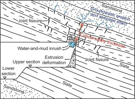
Fig.7 Engineering geological model of the Xinping Tunnel and water-and-mud inrush
3 Design of model test
3.1 Similarity requirements
Physical models must satisfy a series of require‐ments to ensure the essential similarity between the physical model and the prototype.Similarity is con‐sidered in terms of various factors such as the geome‐try,equilibrium and physical equations,boundary conditions,and Newton’s second law.In this study,a reduced dimension scaleCLof 80 and a reduced den‐sity scaleCγof 1 were used in the model.The essen‐tial similarities between the modeling materials and the undisturbed surrounding rock are summarized in Table 3 according to the similarity theory intro‐duced by Li et al.(2020) and Xu et al.(2021).These similarity criteria set the requirements for the modeling materials,such as their specified physical and mechan‐ical properties,test model proportions and size,bound‐ary conditions,and values of the initial stress.Herein,the subscript “p” represents the prototype,and “m”represents the test model.
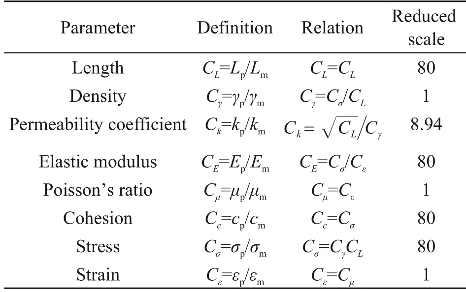
Table 3 Reduced scales of the parameters adopted in the test model
3.2 Model testing system
The model testing system is the main component of testing operation and control.A visualized model testing system of water-and-mud inrush was indepen‐dently designed for this study(Fig.8).It had three com?ponents: a model test bench,a water supply device,and a data collection system.

Fig.8 Design of the model test system of water-and-mud inrush(unit:mm).R is the radius of the tunnel
3.2.1 Model test bench
A transparent box structure was used to construct the test bench with a steel plate at the bottom and high-strength acrylic plates on four sides.The test bench had a height of 1000 mm,a width of 600 mm,and a length of 400 mm(equivalent to the excavation length of 32 m in the Xinping Tunnel).The size was designed according to the geometric similarity ratio(1:80)of the model.The upper and middle parts of the acrylic plates were reinforced with angled iron stiffen‐ers,and the joints were sealed with glass glue to meet the requirements of stiffness,strength,and sealing.The acrylic plates had four Φ10-mm holes on each side.The water-guide hole was on the left,and the lead hole was on the right.The tunnel section was simpli‐fied to a circular section that was 160 mm in diameter(corresponding to the 12.8-m diameter of the Xinping Tunnel).The center of the tunnel was 250 mm from the bottom and 300 mm from the left and right sides.Fig.9 shows a schematic diagram of the model test bench.
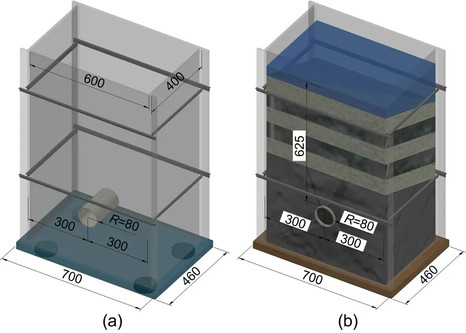
Fig.9 Model test bench (unit: mm): (a) before loading materials;(b)after loading materials
3.2.2 Water supply device
The water supply device was 3 m high and com‐posed of a steel truss,a flexible water tank,and an aqueduct.The flexible water tank was lifted and low‐ered by a chain hoist.The outlet hole at the bottom of the water supply device was connected to the waterguide holes on the left side of the test bench by a hose to produce a stable groundwater environment and pro‐vide variable head heights for the model test.Fig.10 shows a physical figure of the lifting device.
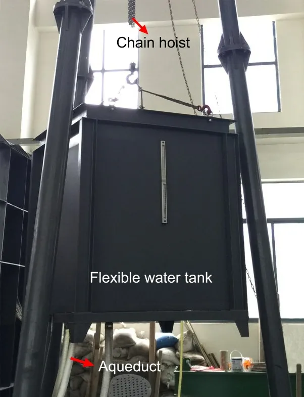
Fig.10 Water supply device
3.2.3 Data collection system
Resistance microsensors were used to track the stress,strain,and seepage pressures of the surround‐ing rock during tunnel excavation.A dynamic and static strain test analyzer was used to collect and ana‐lyze the data during the test.The aqueduct and mea‐suring cylinder were used to collect and measure the flow,respectively.A camera was positioned in front of the test bench at a predetermined distance to record the dynamic change of the surrounding rock during tunnel excavation and the water-and-mud inrush.The data collection system is shown in Fig.11.
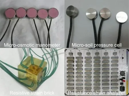
Fig.11 Data collection system
3.3 Similar materials
For this experiment,using appropriate similar materials was key to achieving an accurate simulation.As the mechanical and hydraulic properties of slate and sandstone are very different,it was necessary to prepare two types of similar materials.Materials anal‐ogous to slate would have low permeability,a low soft‐ening coefficient,and low strength,but had to be able to maintain their own strength under water and soil pressure,whereas materials analogous to sandstone would have high permeability and would disintegrate rapidly under groundwater action.
3.3.1 Slate-like materials
Clay and fine sand were selected as aggregate.To manufacture slate-like materials,fiberglass with low water absorption was used as a binder,and water as a regulator.The above materials were combined into standard specimens in different proportions,and their bulk densityγ,elastic modulusE,Poisson’s ratioμ,compressive strengthσt,cohesionc,internal fric‐tion angleφ,and permeability coefficientkwere mea‐sured by laboratory tests.The preparation process is shown in Fig.12.The preparation of clay,fine sand,fiberglass,and water in a mass ratio of 1:1.5:0.02:0.5 met the basic conditions of low permeability and steady performance of slate-like materials,according to ratio tests.The parameters of the slate-like materials are shown in Table 4.
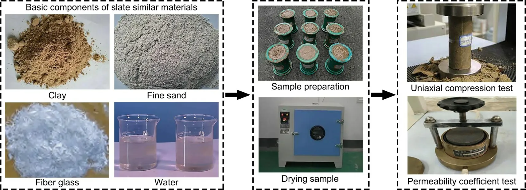
Fig.12 Development of slate-like materials
3.3.2 Sandstone-like materials
The original sandstone rock was broken and could not self-stabilize;therefore,it was prone to collapse under water.Three types of quartz sand with various particle sizes were selected as aggregate,including coarse quartz sand (0.5 mm≤d<5.0 mm),medium quartz sand (0.25 mm≤d<0.50 mm),and fine quartz sand(0.075 mm≤d<0.250 mm).Gypsum was chosen as a binder,as it collapses easily under water.Our ratio experiments found that the ideal mass ratio of coarse sand,medium sand,fine sand,and gypsum was 1:1.3:0.7:0.1.Fig.13 depicts the preparation pro‐cess for sandstone-like materials,and Table 5 lists the parameters.
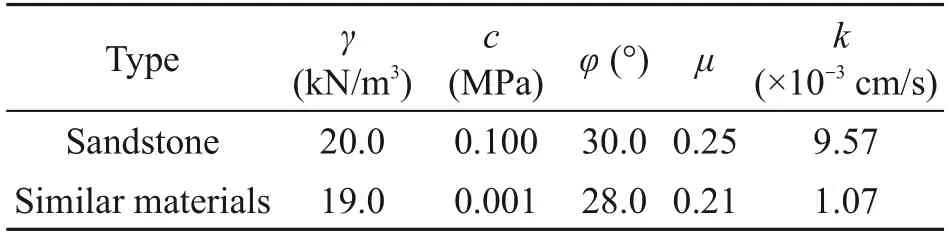
Table 5 Hydrological properties of sandstone and similar materials
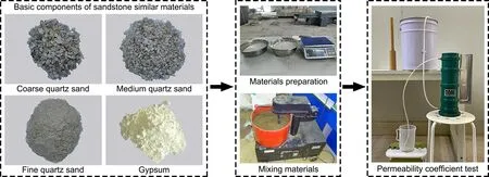
Fig.13 Development of sandstone-like materials

Table 4 Physical and mechanical parameters of slate and similar materials
3.4 Model test scheme
The simulation range for the model test of the Xinping Tunnel was from mileage markers D1K54+990 to D1K54+958 (corresponding to the 400-mm length of the model test bench) with a groundwater level of 50 m (equivalent to 625 mm of the model size).Fig.14 shows a diagram of the test’s structure,in which the size was translated using a geometric similarity ratio.In the test,the tunnel was located in the slate stratum,and the overlying strata were mono‐clinal,bedded strata of slate intercalated with sand‐stone.The stratum height was 44 m(corresponding to the 550 mm in Fig.14),and the dip angle was 20°,which was the same as the direction of tunnel exca‐vation.The slate stratum was regarded as the waterresistant stratum,and the sandstone stratum as the water-bearing stratum.The thickness of the waterresistant stratum was defined as the distance between the floor of the first sandstone water-bearing stratum and the vault of the tunnel.The maximum thickness of the water-resistant stratumLm=136.8 mm before tunnel excavation,corresponded to the actual thick‐ness of 10.9 m of the water-resistant stratum.
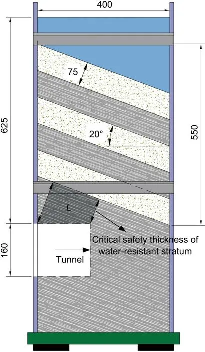
Fig.14 Model test structure diagram(unit:mm)
Micro-soil pressure cells,resistive strain bricks,and micro-osmotic manometers were used in this expe?riment to measure stress,strain,and seepage pressures,respectively,in real time at various locations in the surrounding rock.The key section monitoring method was used in the test.The first half of the tunnel was considered the key region to monitor given the size limitations of the simulation and the impact of inte‐grating excessive monitoring parameters into the anal‐ysis.The layout of the monitoring section is shown in Fig.15.Three monitoring sections were selected for this test,among which monitoring sections I and III were located atX=100 and 200 mm in front of the tunnel,respectively,to monitor the seepage pressure of the surrounding rock.Each monitoring section contained five micro-osmotic manometers.Outside the vault,measuring pointsP1(P6) andP2(P7) were spaced 50 and 100 mm apart,respectively.P3(P8)andP4(P9) were located at 50 and 100 mm outside the spandrel,respectively.The measuring points,which includedP5(P10),were spaced 50 mm apart on theY-axis (the measuring points in brackets represent the monitoring points in monitoring section III).Monitor‐ing section Ⅱwas located atX=120 mm in front of the tunnel,and micro-soil pressure cells and resistive strain bricks were buried at 100 mm on the vault and the spandrel,respectively.All the measuring points of all monitoring sections were in the slate stratum,exceptP7.The measuring pointP7at monitoring section III in the vault was located in the sandstone stratum.
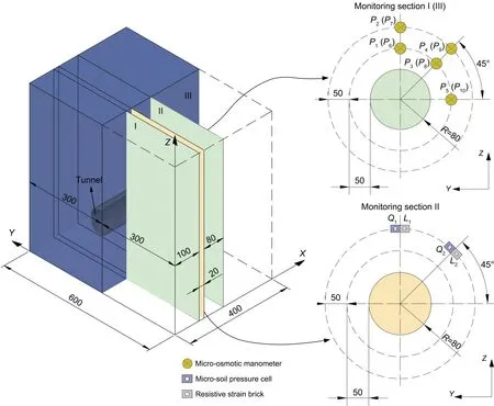
Fig.15 Distribution of monitoring points in the model test(unit:mm)
3.5 Model construction and tunnel excavation process
The primary steps in the construction of the model and the excavation of the tunnel were as follows:
(1) Similar material preparation and model fill‐ing:The model was filled with layers of the prepared materials to simulate the real-world conditions.Evenly mixed materials were poured into the test box in lay‐ers at an incline of 20°.For the strata above the tunnel,the filling height of slate and sandstone was 75 mm.The model body’s density was then strictly controlled by the material quality and filling height.Roughening between layers was essential during the paving of sim‐ilar materials.We were careful to avoid disturbing the monitoring elements in the strata and to prevent the formation of natural seepage channels when tamping down the materials.
(2) Placement of monitoring components: Each monitoring component was buried at the specified loca‐tion and position during the material-filling process.Measurement lines were drawn from the lead hole and connected to the dynamic and static strain analyzer.
(3) Setting up the water-enriched environment:The water supply device was activated so that the sand‐stone stratum would be fully saturated with water.The water flow was paused when the groundwater level reached the design height,and the model body was then left static for 48 h to stabilize the tunnel’s stress and seepage fields.
(4)Tunnel excavation:The tunnel was excavated by manual drilling,using the three-bench method.The excavation length was fixed at 200 mm (correspond‐ing to an excavation length of 16 m in the real tun‐nel),and the length of each excavation footage was 20 mm(corresponding to the actual excavation length of 1.6 m).A total of 24 excavation steps were sched‐uled.The height of the upper bench was 50 mm(cor‐responding to the actual height of 4.0 m of the upper bench),the height of the middle bench was 60 mm(corresponding to the actual height of 4.8 m of the middle bench),and the height of the lower bench was 50 mm(corresponding to the actual height of 4.0 m of the lower bench).Excavation was halted when the footage length had been reached.The excavation depth was then recorded and the thickness of the waterresistant stratum calculated in real time.Excavation of the next footage length was conducted after the data of each monitoring element had been stabilized.The groundwater level was maintained at a constant level during tunnel excavation.If there was a significant change in monitoring data or water seepage at the excavation surface during excavation,excavation was immediately stopped,and the state of the tunnel face was monitored in real time during the water-and-mud inrush process.
4 Results and analysis of the model test
4.1 Analysis of the water-and-mud inrush process
Fig.16 represents the process and phenomena of water-and-mud inrush in the model test.
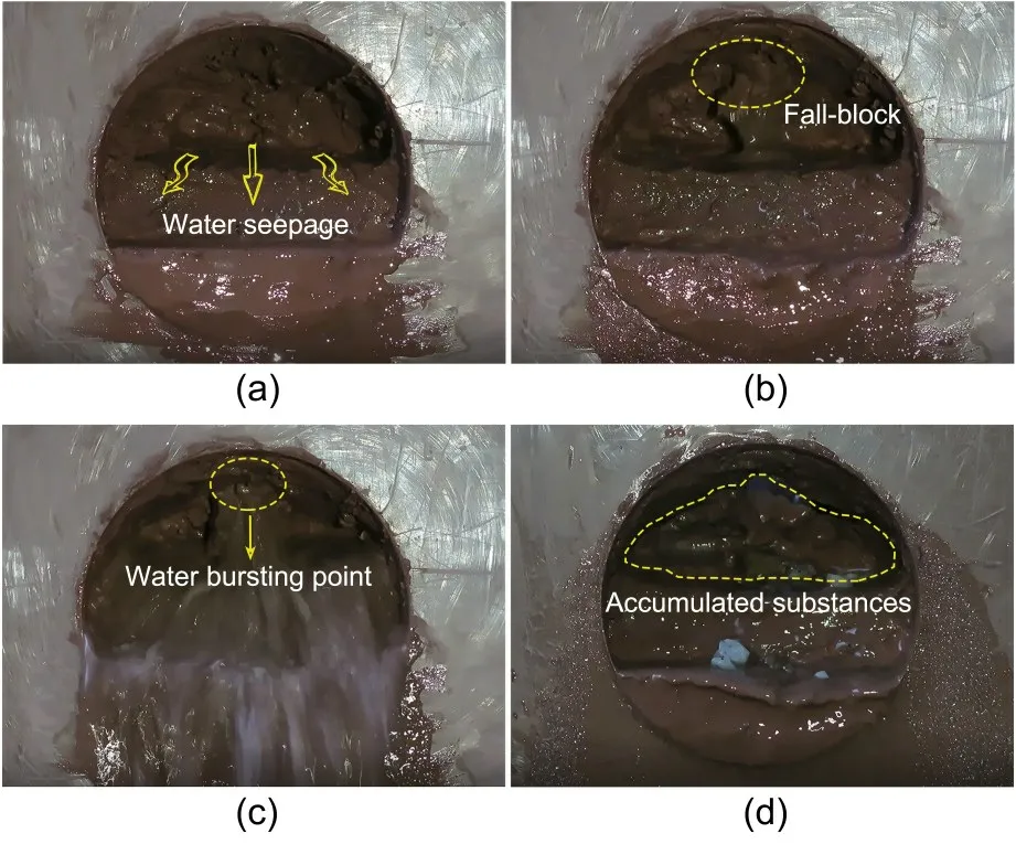
Fig.16 Catastrophic process of water-and-mud inrush:(a) water seepage in the tunnel face;(b) increased water seepage;(c)water-and-mud inrush;(d)end of water-and-mud inrush
The process of water-and-mud inrush was sepa‐rated into three stages based on the experimental char‐acteristics and features.
(1) Seepage stage: When the upper bench had been excavated to a depth ofX=90 mm (correspond‐ing to the thickness of the water-resistant stratumL=106 mm),new micro-fissures were generated in the surrounding rock,existing fissures were expanded,and a tiny amount of water seepage developed on the vault.However,as the tunnel face advanced,the water seepage channel closed,and the water seepage of the vault disappeared briefly.When the upper bench was excavated to the position ofX=120 mm (correspond‐ing to the thickness of the water-resistant stratumL=95.7 mm),the water seepage channel expanded again,and the water seepage on the vault increased(Fig.16a),due to the combined action of surrounding rock unload‐ing,the water and soil pressure,and the groundwater permeability.
(2) High-leakage flow stage: When the upper bench had been excavated to the point ofX=150 mm(corresponding to the thickness of the water-resistant stratumL=85.5 mm),the water seepage of the vault switched to a runoff state.Meanwhile,on the vault,a water-conducting channel developed and released a stream of dirty water.At this point,the excavation was halted.The water-conducting channel grew as a result of the seepage–stress coupling,and sandstone debris was removed by the underground flow.The rock sur‐rounding the vault fell and even collapsed in parts,followed by a minimal flow of mud (Fig.16b).The water-conducting channel eventually became inte‐grated and further damaged the surrounding rock on the vault leading to a water-and-mud inrush disaster,with a large amount of water–sand mixture gushing into the tunnel from the vault.The water-and-mud inrush is shown in Fig.16c.Although the occurrence of the water-and-mud inrush was sudden,the waterconducting channel experienced a long process of infiltration damage from expansion to connection.
(3)Attenuation stage:The magnitude of the disas‐ter and the flow of water-and-mud inrush steadily diminished over time,and the water quality gradually changed from turbid to limpid.The water-and-mud inrush stopped when the overlying sandstone had com‐pletely discharged all of its groundwater,which was not efficiently replenished.In the end,a substantial volume of sand mixture accumulated at the tunnel face(Fig.16d).
To facilitate a clearer and intuitive understand‐ing of the process and phenomena of the model test,the excavation length and the thickness of the waterresistant stratum at key excavation steps are summa‐rized in Table 6,as well as experimental phenomena.The corresponding actual dimensions are included.
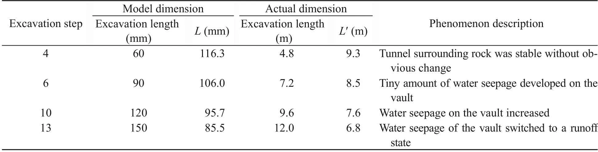
Table 6 Description of model test process
4.2 Stress–strain variation characteristics
The stability of the surrounding rock is reflected by the variation in strength after structural failure and weakening.As a result,the stress–strain curve of the surrounding rock during tunnel excavation was used to assess the stability characteristics.Fig.17 shows the stress–strain curves of the tunnel vault and spandrel of monitoring section II,with the strain energy density of the surrounding rock represented by the area under the stress–strain curve.
(1) The stress–strain curve of the vault showed an increasing trend during tunnel excavation fromX=0 to 90 mm (Fig.17).There was an initial in-situ stress of 6.5 kPa in both the vault and spandrel due to the influence of overlying water and soil pressure.The vault’s stress was rapidly released,and the excavation disturbed the surrounding rock,causing stress redistri‐bution.As the tunnel face advanced,the stress–strain curve of the vault had a slow-to-quick growth trend as the vault’s stress shifted rapidly from low to high.The water-conducting channel extended and connected when the tunnel had been excavated toX=150 mm,causing water-and-mud inrush.Any changes in vault stress were insignificant when the strain increased.The stress–strain curves on the vault and the spandrel showed a similar response,but the vault reached criti‐cal failure stress atX=150 mm,before the spandrel.
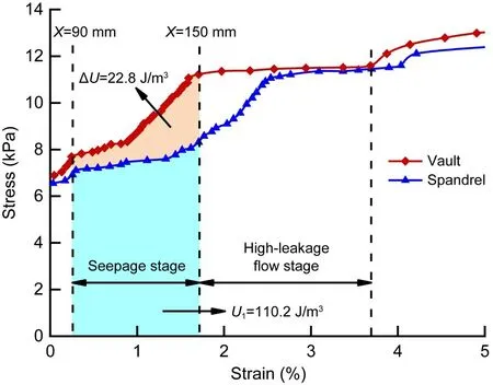
Fig.17 Stress–strain curves during tunnel excavation.ΔU is the difference of strain energy density between vault and spandrel;U1 is the strain energy density of spandrel
(2)The stable states of surrounding rocks varied depending on their stress conditions.To some extent,the strain energy density of the surrounding rock refl?ected its stability.Therefore,as the strain energy den‐sity increased,the stability of the surrounding rock weakened.In this case,there was a significant possi‐bility of water-and-mud inrush.The strain energy den‐sity of the vault was 20.7%more than that of the span‐drel,according to an examination of strain energydensity at the location of the water-and-mud inrush.This conclusion was supported by the position of the water-and-mud inrush on the tunnel vault.
4.3 Variation characteristics of the seepage field
Figs.18 and 19 demonstrate the variable features of seepage pressure and flow in monitoring sections I and III at various excavation distances.
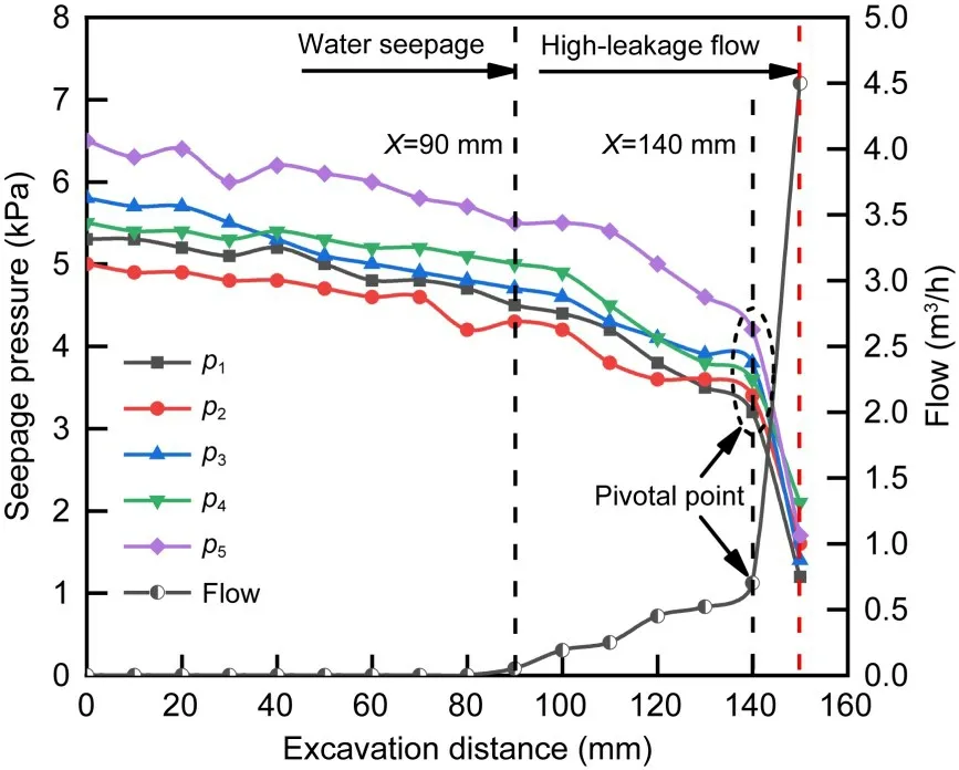
Fig.18 Characteristic curves of seepage pressure and flow at different excavation distances of monitoring section I
(1)In general,as tunnel excavation distance incr?eased,the change trend of seepage pressure at each monitoring site followed a similar pattern,namely,a slow reduction,then a rapid reduction,and finally,an abrupt change.However,the trend of the flow grad‐ually shifted from stable and constant to gradually increasing,until suddenly altering.
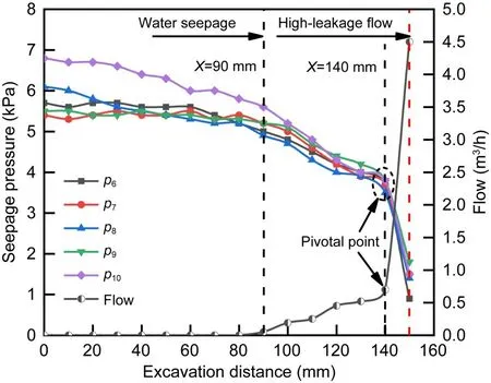
Fig.19 Characteristic curves of seepage pressure and flow at different excavation distances of monitoring section III
(2) The sandstone and slate interbedded strata were in a stable seepage field before tunnel excava‐tion.When tunnel excavation began,the excavation disturbance and unloading of the surrounding rock caused the tunnel seepage field to alter,and the seep‐age pressure gradually decreased.The flow increased from zero as the tunnel was excavated toX=90 mm,suggesting that initiation and development of fissures in the surrounding rock led to an increase in the water seepage capacity.The continuous expansion of surro?unding rock fissures provided a water seepage channel for groundwater as the tunnel face reachedX=140 mm,which in turn increased the seepage failure.At each monitoring site,the flow and seepage pressure changed abruptly.When the tunnel was excavated toX=150 mm,a water-and-mud inrush disaster occurred,and the flow instantly increased from 0.7 to 4.5 m3/h,a 5.4-fold increase.The seepage pressure at monitoring pointsP1andP6of the vault decreased the most,by 62.5%and 75.7%,respectively.This change was brief and rapid,and the range in variation of the seepage pres‐sure and flow was large,which was consistent with the features of strong concealment and then sudden and powerful destruction caused by the water-and-mud inrush disasters in the Xinping Tunnel.
4.4 Effect of water-resistant stratum thickness
The water-resistant stratum was the final barrier preventing a water-and-mud inrush disaster,and its thickness determined whether or not a disaster would occur.To determine the influence of the thickness of the water-resistant stratum on the evolution characteristics of seepage pressure and flow during tunnel excavation,monitoring data fromP1,P3,andP5of monitoring sec‐tion I andP6,P8,andP10of monitoring section III were selected to draw the relationship curves among the seepage pressure,the flow,and the thickness of the water-resistant stratum(Fig.20).
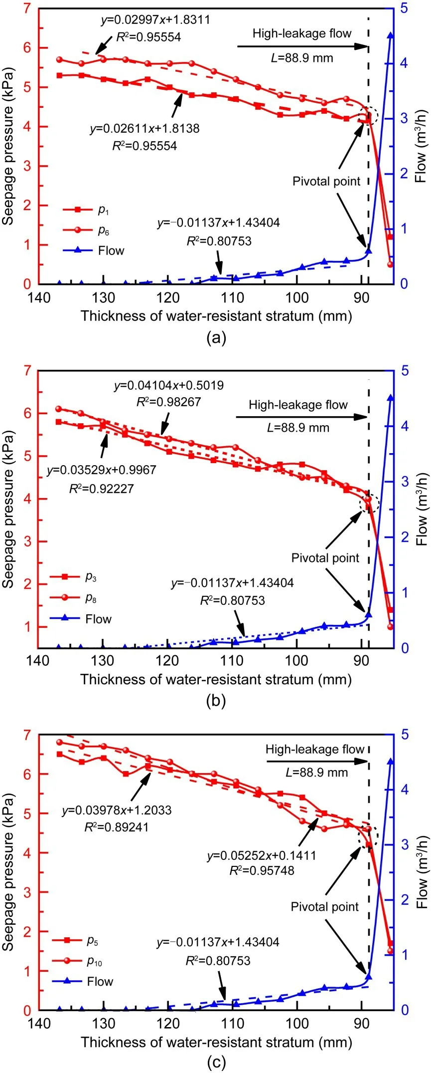
Fig.20 Relationships among seepage pressure,flow,and the thickness of water-resistant strata: (a) monitoring points P1 and P6;(b) monitoring points P3 and P8;(c)monitoring points P5 and P10
Before tunnel excavation,the initial thickness of the water-resistant stratum was 136.8 mm(correspond‐ing to the actual maximum thickness of 10.9 m of the water-resistant stratum).When the water-and-mud inrush disaster occurred,the thickness was 85.5 mm(corresponding to the actual thickness of 6.8 m of the water-resistant stratum).The thickness of the waterresistant stratum had a positive linear relationship with the seepage pressure and a negative linear rela‐tionship with the flow at each monitoring station.With the reduction in thickness,the seepage pres‐sure gradually dropped.The fitted linear correlation coefficients between the seepage pressure and the thickness of the water-resistant stratum were greater than 0.8.These results suggest that the initial frac‐ture and the new fracture expanded more easily as the thickness of the water-resistant stratum was reduced.The permeability resistance of the surrounding rock reduced over time,as did the bearing capability of the rock against the water and soil pressure.The seepage pressure of the surrounding rock abruptly altered as the thickness of the water-resistant stratum was reduced to the critical safety thickness.At this point,only a small amount of seepage pressure was required to destroy the water-resistant stratum,result‐ing in the water-and-mud inrush.
Fig.21 further shows the relationship between the seepage pressure and the flow of the surrounding rock when the thickness of the water-resistant stra‐tum was reduced.There was a negative correlation between seepage pressure and flow,as well as two highly concentrated regions: a “high-seepage pressure and low-flow” area and a “l(fā)ow-seepage pressure and high-flow”area.In other words,both seepage pressure and flow had a pivotal point where the seepage pres‐sure decreased from high to low,and the flow rose from low to high.This point was regarded as the char‐acteristic point of deterioration of the water-resistant stratum,and the thickness of the water-resistant stra‐tum corresponding to this point was the critical safety thickness.In the model test,the critical safety thick‐ness of the water-resistant stratum was 88.9 mm(cor‐responding to the actual critical thickness of 7.1 m of the water-resistant stratum).
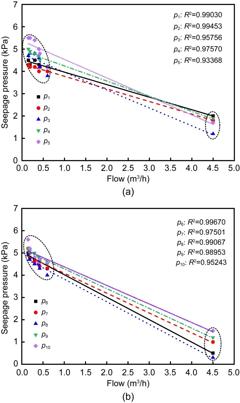
Fig.21 Relationships between the seepage pressure and flow of each monitoring section: (a) monitoring section I;(b)monitoring section III
There was a good linear relationship between the seepage pressure and the flow,which indicated that the seepage process of the model test conformed with Darcy’s law.Therefore,the permeability coefficient and hydraulic gradient of the surrounding rock could be calculated according to Darcy’s law.Fig.22 showed the change rule of hydraulic gradient and permeability coefficient of the surrounding rock(monitoring sec‐tions I and III) during the reduction of the thickness of the water-resistant stratum.The variation curves of the hydraulic gradient and permeability coeffi‐cient both showed obvious segmental characteristics with the decrease of the thickness of the water-resistant stratum (Fig.22).Before the high-leakage flow,with the decrease of the thickness of the water-resistant stratum,the hydraulic gradient changed slightly and the permeability coefficient was basically unchanged.After the high-leakage flow,the hydraulic gradient decreased sharply,while the permeability coefficient increased rapidly.Therefore,after the thickness of the water-resistant stratum was reduced to the critical safety thickness,the permeability coefficient of the surrounding rock increased rapidly,the hydraulic gradient decreased sharply,the water-resistant capacity of the surrounding rock decreased sharply,and the sur‐rounding rock was damaged by seepage.The smaller the thickness of water-resistant stratum,the greater the risk of water-and-mud inrush.The process of the water-and-mud inrush is an evolutionary process in which the water-resistant stratum gradually loses its water-resistant capacity.
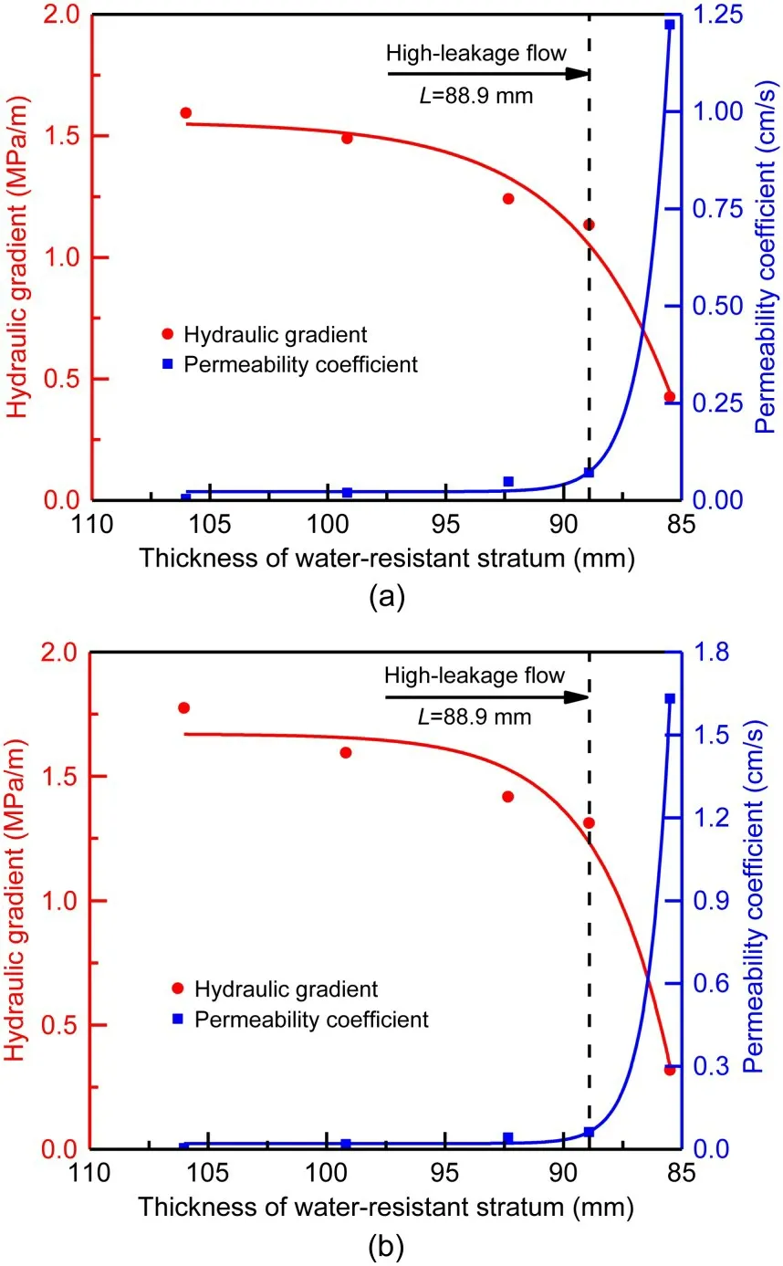
Fig.22 Change rule of hydraulic gradient and permeability coefficient: (a) monitoring section I;(b) monitoring section III
5 Conclusions
In this study,we examined the mechanisms under‐pinning water-and-mud inrush disasters during the construction of tunnels in sandstone and slate inter‐bedded Presinian strata.A physical model test was conducted based on the water-and-mud inrush disas‐ters in the Xinping Tunnel on the China–Laos Rail‐way.The main conclusions were as follows:
(1) An engineering geological model in sand‐stone and slate interbedded Presinian strata was built based on the engineering characteristics and geologi‐cal conditions of the Xinping Tunnel.Materials similar to slate and sandstone that matched the test require‐ments were developed.The model test successfully reproduced the process of water-and-mud inrush in the field of practical engineering.
(2)The process of water-and-mud inrush in sand‐stone and slate interbedded Presinian strata was divided into three stages: seepage stage,high-leakage flow stage,and attenuation stage.In the process of the water-and-mud inrush,parameters such as the stress–strain,seepage pressure,and flow of the surrounding rock had stage-related characteristics,which indicated the disaster’s formation,development,and evolution.
(3)As the tunnel face advanced,the trend of the stress–strain curve of the surrounding rock increased from slow to steep,and the characteristics of strain energy density revealed the erosion and weakening effect of groundwater on the surrounding rock.The strain energy density of the vault was 20.7% higher than that of the spandrel at the seepage stage.As the strain energy density of the surrounding rock incre?ased,the surrounding rock weakened,and the risk of water-and-mud inrush due to seepage failure increased.
(4)The seepage pressure had a positive linear relationship while the flow had a negative linear rela‐tionship with the thickness of the water-resistant stra‐tum.In the process of changing seepage pressure and flow,there was a pivotal point.Before this point,the formation of the high-leakage flow channel had a slow seepage failure process.The permeability pressure of the surrounding rock reduced significantly after the pivotal point,whereas the permeability coefficient of the water-resistant stratum rapidly increased.The pivotal point was regarded as the characteristic point of deterioration of the water-resistant stratum,and the thickness of the water-resistant stratum corre‐sponding to this point was determined to be the criti‐cal safety thickness.The critical safety thickness of the water-resistant stratum was 88.9 mm in the model test.
(5)The water-and-mud inrush disaster of a tunnel in sandstone and slate interbedded Presinian strata was related not only to the properties of the surrounding rock,but also to the excavation disturbance and ground‐water action.The water-and-mud inrush is a cata‐strophic process induced by the action of excavation unloading and in situ stress–seepage coupling,in which the water-resistant stratum reaches the critical safety thickness,a high-leakage flow channel forms,and the water-resistant stratum gradually fails.
Acknowledgments
This work is supported by the National High-Speed Rail United Foundation of China(No.U1934213).
Author contributions
Peng XU and Zhi-qiang ZHANG designed the research.Peng XU and Peng PENG were responsible for the model test and paper writing.Rong-hua WEI processed the corresponding data.Zhi-qiang ZHANG helped to organize the manuscript.Peng XU revised and edited the final version.
Conflict of interest
Peng XU,Peng PENG,Rong-hua WEI,and Zhi-qiang ZHANG declare that they have no conflict of interest.
 Journal of Zhejiang University-Science A(Applied Physics & Engineering)2022年11期
- Journal of Zhejiang University-Science A(Applied Physics & Engineering)的其它文章
- Visualizing the dynamic progression of backward erosion piping in a Hele-Shaw cell
- Evaluation of heavy roller compaction on a large-thickness layer of subgrade with full-scale field experiments
- Frozen sand–concrete interface direct shear behavior under constant normal load and constant normal height boundary
- Shaking table tests on a cantilever retaining wall with reinforced and unreinforced backfill
- Soil effect on the bearing capacity of a double-lining structure under internal water pressure
- Influence of groundwater level changes on the seismic response of geosynthetic-reinforced soil retaining walls