
Experimental study of a low-pressure hybrid RF discharge
2020-06-14 08:45:34ElenaKRALKINAPolinaNEKLIUDOVAVladimirPAVLOVKonstantinVAVILINIlyaZADIRIEVandChenZHAO
Plasma Science and Technology 2020年5期
Elena KRALKINA,Polina NEKLIUDOVA,Vladimir PAVLOV,Konstantin VAVILIN,Ilya ZADIRIEV and Chen ZHAO
Physical Electronics Department,Faculty of Physics,Lomonosov Moscow State University,119991 Moscow,Russia
Abstract
Keywords:radio-frequency,discharge,plasma,E-mode,H-mode
1.Introduction
Low-pressure inductive RF plasma sources are important components of modern ion-beam and plasma technologies.Numerous technological applications of the discharge stimulate interest in a detailed study of its physical properties,and in particular,in studying the effect of the capacitive component of the discharge on its parameters.
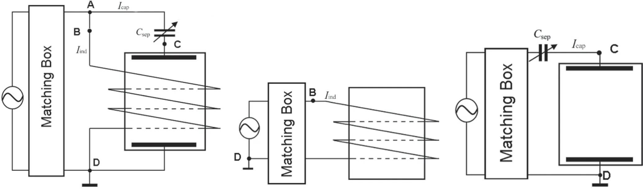
Figure 1.The scheme of experiments with (a) hybrid,(b) inductive,and (с) capacitive discharges.
The role of capacitive component in ignition and maintenance of the inductive RF discharge has been discussed for over 100 years [1–4].In-depth studies of discharges with independent inductive and capacitive channels were carried out in [5–8]due to the wide utilization of the inductive plasma reactors with capacitively biased substrate.It was shown that the presence of an independent capacitive channel powered by an independent RF power source led to the decrease in the threshold of E- to H- transition.The bias induced the increase in the electron density at low RF power and decrease in electron density at high RF power.In turn,the increase in the RF power coupled to plasma through the inductive channel led to the decrease in the absolute value of the voltage drop near the biased electrode [8].In [9],the power transfer efficiency and mode jump in an inductive RF discharge were studied experimentally using external and plasma-immersed internal antennas.The internal antenna showed higher power efficiency and enabled a stable discharge without a density jump.In case of external antenna,a density jump was recorded.It was attributed to the discharge mode transitioning from capacitive to inductive.The theoretical model presented in [6]gave an opportunity to explain the mechanism of the density jump in terms of the plasma density dependence on the power transfer efficiency.In [10],the transition from E- to H-mode in inductive discharge in oxygen was studied using space- and phase-resolved optical measurements.The radiation emission,measured phaseresolved,allowed one to investigate the electron dynamics within the RF cycle.In the E-mode of the discharge,peaks of optical emission attributed to the formation of fast electrons were detected.In the H-mode,two excitation maxima were observed during the RF cycle,which corresponded to the acceleration of electrons along a ring-shaped trajectory,moving in opposite directions during each half of the RF cycle.In accordance with[10],fast electrons produced during the transition provide additional excitation and ionization,which result in the increase in electron density and simplification of achieving the H-mode.In[11],the alpha capacitive mode was observed at low RF powers.Increasing the RF source power led to the transition to the gamma capacitive mode and appearance of avalanches of fast electrons.At high RF powers,transition to the inductive mode took place.
It is seen that in the inductive RF discharge,even one sustained in H-mode,a capacitive RF power deposition channel inevitably forms due to the presence of parasitic capacitances between the antenna coils and the plasma.These parasitic capacitances lead to several physical effects:formation of a voltage drop near the location of the antenna,generation of fast electrons in the discharge and coupling of a fraction of RF power through the capacitive channel.The presence of the capacitive channel changes the antenna current and the plasma parameters that,in turn,determine the fraction of the source power coupled to the plasma through the inductive channel.In the majority of recent works[12,13],a metal screen with apertures is used to decrease the capacitive coupling between the antenna and the plasma.In[14],we studied the effect of capacitive coupling in two discharge schemes.In the first case,the inductive and capacitive channels were powered by two independent RF power sources.In the second case,the inductor and capacitor plates,which were the main parts of inductive and capacitive channels,were connected in parallel to the same RF power source.The second modification of RF discharge was called a hybrid one.It is worth mentioning that a hybrid discharge can be considered as a model of a real RF inductive discharge necessarily possessing parasitic capacitive channel.
Experimental studies carried out in [15,16]showed that the presence of an independent capacitive channel changes the fraction of the source power coupled to the plasma through the inductive channel.This manifests in the decrease in the critical power Pcritcoupled through the inductive channel,at which the discharge transitions from Е- to Нmode.At the same time,it was shown in [17]that the presence of an inductive discharge channel affects the electrode voltage drop,decreasing it.
Results obtained in [15–17]showed that the simultaneous use of both inductive and capacitive components of RF discharge provides a possibility to smoothly manage its parameters,which is important in many technical applications.The objective of this work is a detailed study of the influence of the external circuit parameters on the parameters of the plasma of the hybrid RF discharge.
2.Experimental methods
In this work,we used a 15 cm diameter and 15 cm long cylindrical glass plasma source.The upper end of the source was covered with a dielectric flange and the lower end was covered with a metal screen with apertures used to evacuate the source and supply the working gas(argon).The discharge was maintained using a water-cooled spiral antenna (solenoidal antenna with inductance 2.4 μHn) located on the side surface of the source.In addition to the solenoidal antenna,we placed capacitor plates on the upper and lower flanges of the plasma source (see figure 1(a)).The separating variable capacitor Csepwas connected in series with capacitor plates on the flanges.It was included into the electrical circuit of the capacitive channel in order to control its contribution to discharge sustaining.The inductor and capacitor plates with Csepwere connected in parallel to the RF power supply through a matcher.Further,we refer to this discharge type as the hybrid discharge[14].The electrical diagram of the matching box is shown on figure 2.
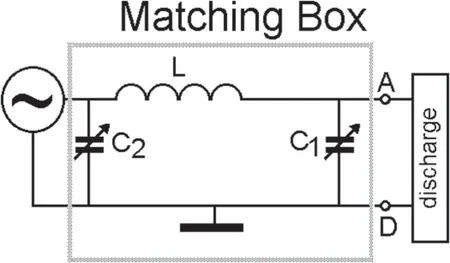
Figure 2.The electrical diagram of the matching box.
The operating frequency of the RF power supply was 13.56 MHz and its output power could be varied in a continuous range of 0–1000 W.A Rogowski coil installed in point B (figure 1) was used to measure the antenna current Iind.The second Rogowski coil was connected to the circuit of the loaded (active) capacitor plate in point C to measure the current flowing in the capacitive channel Icap.
The measured values of Iindand Icapamplitude and phase were used to determine the impedance of the inductive Zindand capacitive Zcapchannels,respectively.
In parallel with the measurements of RF voltage between the electrodes of the capacitive channel(points C and D),we determined the DC bias UCDof the loaded electrode in respect to the grounded(passive)electrode using a VU-15 voltmeter.The high resistance of the voltmeter gave us the opportunity to avoid closing of the electrodes by DC current and to eliminate the discharge disturbance.
We compared the plasma parameters of the hybrid discharge with those of inductive and capacitive discharges that were ignited and maintained in the same plasma source (see figures 1(b)and(c)).The same RF power source and variable separating capacitor Csepwere used.A Rogowski coil installed in point B was used to measure the antenna current Iindin case of hybrid and pure inductive discharges.A Rogowski coil connected into the circuit of the loaded plate in point C measured the current Icapin case of the pure capacitive discharge.RF voltages at the output of the matching box (points A and D) as well as between the discharge capacitor plates (points C and D) were measured using capacitive dividers.
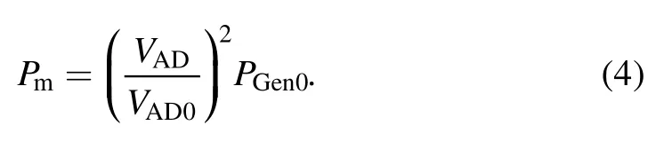
In real experiments with a hybrid discharge,a significant part of the power is lost in the matching system Pmand due to the antenna heating Pant.The expression for the power balance takes the form:

where Pplis the RF power coupled to plasma.
Power losses in the matching system Pmcan be determined by the formula [18]based on the fact that matching system is linear:
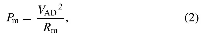
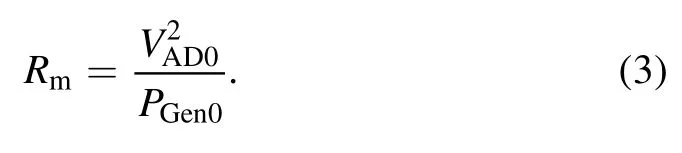
where Rmis the effective resistance that defines the power losses in the matching box.The value Rmwas determined by measuring VAD0and RF generator power PGen0without discharge using only capacitive discharge circuit (see figure 1(c)).In this case:
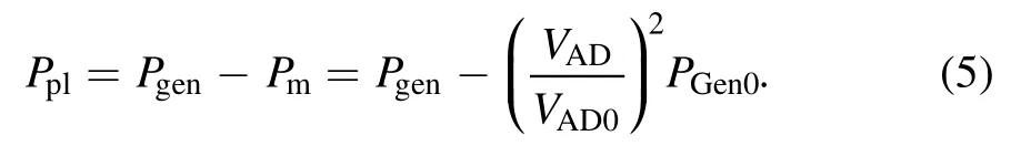
Thus,in the presence of a discharge,the power losses in the matching system can be determined by the formula:
In a hybrid RF discharge some power is also lost when the inductor is heated.In this connection,correct accounting of power losses in the external discharge circuit requires first determination of Rmusing only the capacitive discharge circuit,and then Pantdetermination using the standard procedure[15],where instead of values PGen0the valuesPGen0-Pmare used.However,experiments showed thatPant?Pm,so the following expression was used for Ppldetermination:
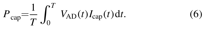
In parallel the RF power value released in the capacitive channel was determined.For this purpose,the instant values of current Icapand voltage VADmeasured in the capacitive circuit were integrated over the period of the RF field to determine the power Pcapreleased in the capacitive channel:
The plasma parameters were monitored using a Langmuir probe.The probe was a 0.3 mm diameter tungsten wire covered with glass,except for a 5 mm long segment at its end.We used a standard electric circuit usually employed for such measurements.To avoid the distortion of the measured probe characteristic,resonant high-resistance filters were used at the fundamental and second harmonics of the power source frequency.Measurement results were supplied to an AD converter connected to a PC.
During the experiments,plasma radiation intensity along the source axis was also recorded.A ruler with a set of apertures was placed in front of the plasma source.Plasma radiation from the chosen point through an optical fiber was supplied to the entrance slit of a monochromator whose output slit was connected to a photomultiplier.The signal from the photomultiplier was supplied to an AD converter.The spatial resolution of the measurements was no worse than 1.5 cm.
The spectrum was scanned in the wavelength range of 350–750 nm.In experiments with electron density lower than 1011cm–3,we used an independent spectral method to determine the effective temperature of fast electrons from the ratio of spectral lines intensities.Assuming that,in our case,the plasma coronal model is applicable,the intensity of each spectral line is proportional to the quantity of emitted photons and the energy of every photon [19].In this case,the ratio between two spectral lines intensitiesI1andI2takes the form
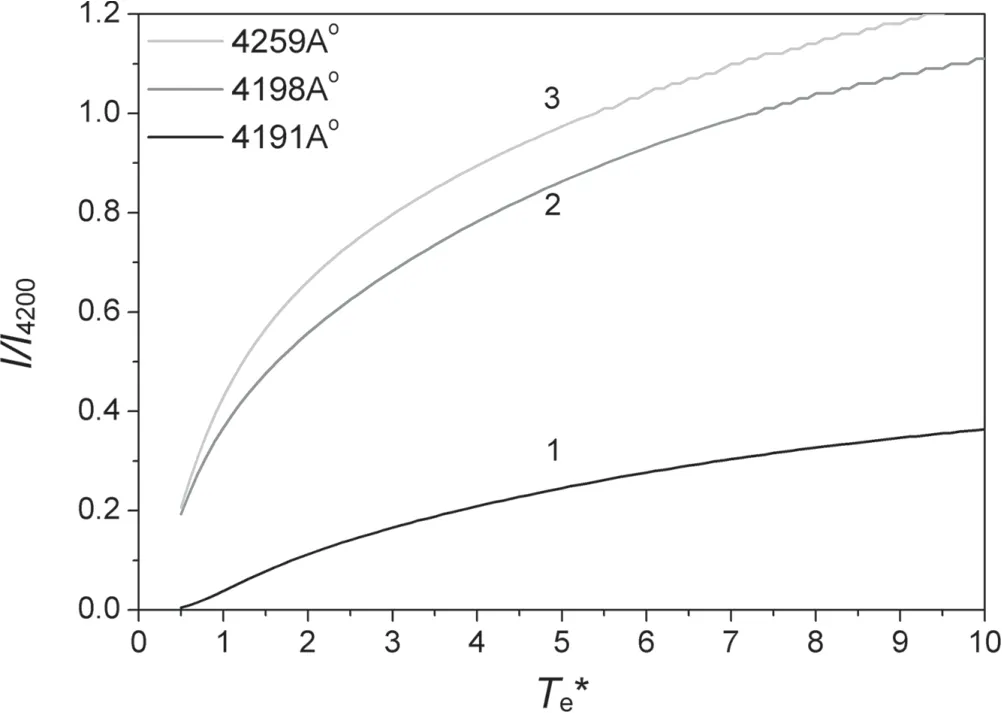
Figure 3.Dependence of the ratio of Ar I spectral line intensities to Ar I 4200 ? line intensity on electron temperature Те*.1—I4191/I4200,2—I4198/I4200,3—I4259/I4200.
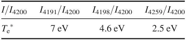
Table 1.Effective temperature of fast electrons obtained from ratio of different spectral lines intensities.
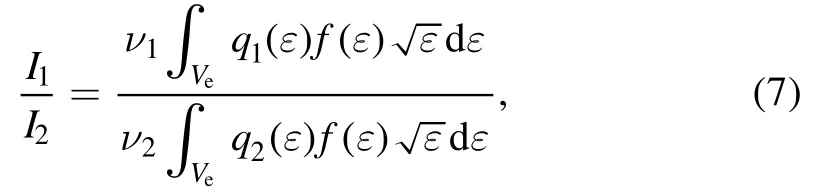
whereν1andν2are the frequencies of the spectral lines andq1andq2are their excitation cross sections.Assuming that the EEDF is Maxwellian and using the reference data[20]on the effective excitation cross section for argon spectral lines,we calculated the line intensity ratio (7) as a function of the electron temperature.The resulting calibration curves are shown in figure 3.
Preliminary probe measurements carried out in pure inductive discharge under conditions that the EEDF was close to Maxwellian showed that the electron temperature was equal to 4.5 eV.The effective temperature of fast electrons Te*obtained from the ratio of Ar I spectral lines intensities under the same conditions are represented in table 1.It is seen that the ratio of 4198 and I 4200 ? line intensities is closer to that determined from probe measurements than the ratio of other lines.Therefore,the ratio between these lines intensities was used in this study to estimate the effective electron temperature.Since the wavelengths of these lines were close,we could avoid calibrating the spectral system in absolute value.Experiments were carried out in argon in the pressure range of 7–80 mTorr at working RF power source frequency of 13.56 MHz.
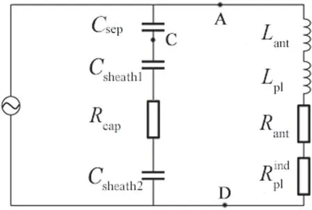
Figure 4.The equivalent diagram of the hybrid discharge.
3.Equivalent diagram of a hybrid RF discharge
Before starting the description of the experiments,it is worth considering the simplified equivalent diagram of the hybrid discharge proposed in [14].It is shown in figure 4.The inductive discharge channel is represented as an electrical circuit consisting of the inductance of the antenna Lant,the equivalent inductance of the plasma Lplconnected in series with the active antenna resistance Rantand the equivalent plasma resistanceThe capacitive discharge channel of the discharge is formed by the separating capacitor Csepincluded in the external discharge circuit,near electrode sheaths with capacitances Сsheath1,Сsheath2,and active plasma resistance Rсap.Note that Rсapandare determined by the same set of plasma parameters.
The equivalent diagram shown in figure 4 is valid only under the supposition that RF power through the inductive channel is coupled to the discharge due to the excitation of the inductive RF fields in plasma.Under small power of the RF generator it can happen that inductive channel is not formed and the power is coupled to plasma due to parasitic capacitances between antenna coils,between antenna and plasma,etc.
The power Pplis coupled to the plasma through both channels and is equal to
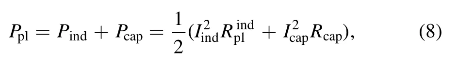
where Pindand Pcapare the power values coupled to the plasma through the inductive and capacitive channels;Iindand Icapare the currents flowing through the inductive and capacitive channels,respectively.
Using the simplified equivalent circuit of the hybrid RF discharge,it is easy to obtain expressions for the impedances of the inductive Zindand capacitive Zcapchannels:
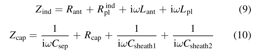
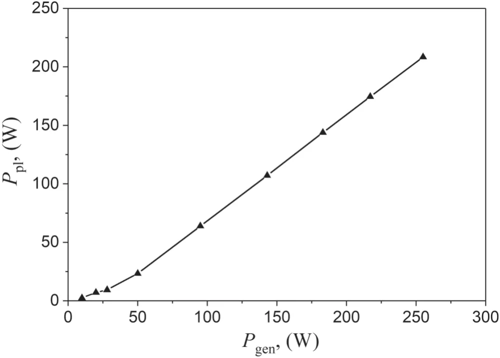
Figure 5.The RF power value coupled to plasma versus RF generator power.Csep=50 pF.Ar pressure is 7 mTorr.Ppl values were obtained using formulas (1)–(5).

It is natural to call the valueequivalent resistance of the hybrid discharge by analogy with the RF inductive discharge becauseconnects the power coupled to plasma with the current flowing through antenna.However,in the case of a hybrid discharge,the equivalent plasma resistance depends not only on the patterns of the RF fields penetration into the plasma and the power absorption mechanism,but also on the parameters of the external discharge circuit.The parameters of the external circuit are included in the expressions for the impedance of the inductive and capacitive channels and significantly affect the relative role of each of the channels in maintaining the hybrid discharge.
4.Experimental results
Regarding the equivalent diagram of a hybrid discharge we see that the change of the RF generator power and separating capacitor capacitance must lead to the change of the ratio between RF power values coupled to plasma through inductive Pindand capacitive Pcapdischarge channels.This happens because RсapandRplindas well as Сsheath1,Сsheath2,Lpldepend on electron density neand temperature Tethat in turn depend on Pgen,Pind,Pcapand Csep.To clarify the relationship of the mentioned parameters we started experiments from the determination of the patterns of the RF power coupling to discharge.
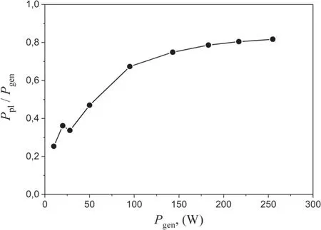
Figure 6.The RF power coupling efficiency versus RF generator power.Csep=50 pF.Ar pressure is 7 mTorr.Ppl values were obtained using formulas (1)–(5).
4.1.The patterns of the RF power coupling to discharge
First the Pplvalues were obtained using formulas (1)–(5) for different RF generator power and Csepvalues.Figures 5 and 6 show the determined Pplas well as RF power coupling efficiency Ppl/Pgenin dependence on Pgenmeasured for Csep=50 pF.Both Ppland Ppl/Pgenvalues increase with the growth of the RF generator power.However,the growth rate of Ppl/Pgensignificantly slows down provided that Pgenexceeds 100 W.It approaches 80% at Pgen> 200 W.
Now let us consider the behavior of the RF power portion coupled to the discharge through the capacitive channel Pcap/Ppl.Figure 7 shows that at low Ppl,the ratio Pcap/Pplis relatively high,i.e.Pcapis about 20% of Ppl.Then,with increasing Ppl,the deposition of RF power through the capacitive channel decreases,at this time the deposition through the inductive channel at small Csepbecomes overwhelmingly large.In case of the inductive RF discharge such effect is attributed to the discharge transition from the E- to H-mode.The increase of the separating capacitance leads to the shift of the position of the transition from the mode with small Pcap/Pplto higher Ppland to the growth of Pcap/Pplvalue after the transition.Here the ratio Pcap/Ppldoes not change its value within experimental error.The growth of the argon pressure to 78 mTorr makes the discharge more‘inductive’ due to the decrease of the Pcap/Pgenvalue.
The results obtained with the Csepequal to 314 pF at argon pressure 16 mTorr at small values of RF generator power differ from that mentioned above.Instead of decreasing the ratio Pcap/Pgenincreases with Pgen.This fact is most probably due to the fact that at small RF generator power the inductive channel is not formed yet and the RF power is coupled to discharge through two capacitive channels.The second capacitive channel appears due to the parasitic capacitance between antenna coils,coils and plasma.
In order to understand the patterns of Pind/Pcapvariation with Pgenlet us rewrite equation (8) expressing Icapthrough Iindand impedances of the inductive and capacitive channels Zind,ZAD:
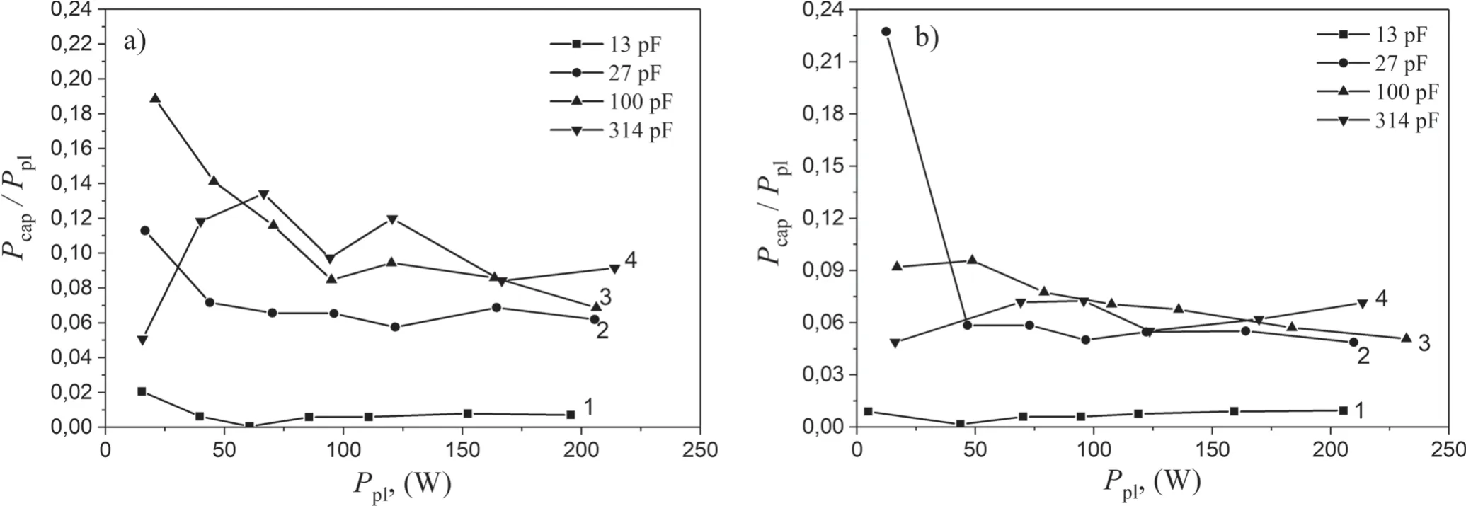
Figure 7.Pcap/Ppl versus total RF power coupled to plasma.Hybrid discharge.Ar pressures:(a) 7 mTorr,(b) 78 mTorr;(1) Csep=13 pF,(2) Csep=27 pF,(3) Csep=100 pF,(4) Csep=314 pF.Ppl values were obtained using formulas (1)–(5),Pcap values were obtained using formula (6).
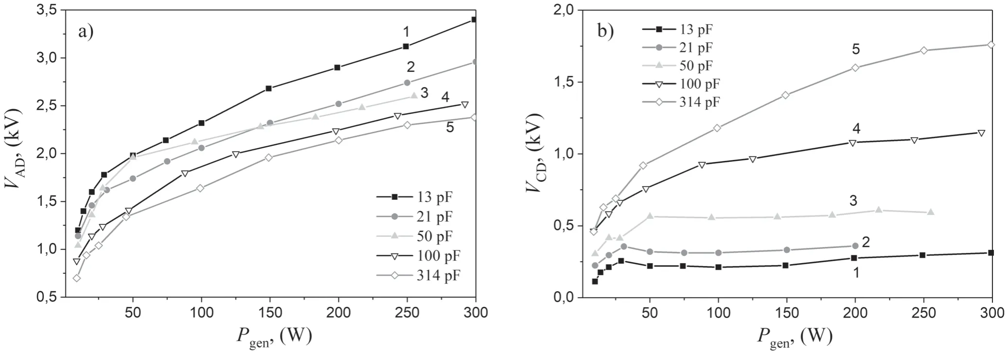
Figure 8.Dependences of RF voltage between points A and D(a),between points C and D(b)on the RF generator power.Hybrid discharge.Argon pressure is 7 mTorr;(1) Csep=13 pF,(2) Csep=21 pF,(3) Csep=50 pF,(4) Csep=100 pF,(5) Csep=314 pF.
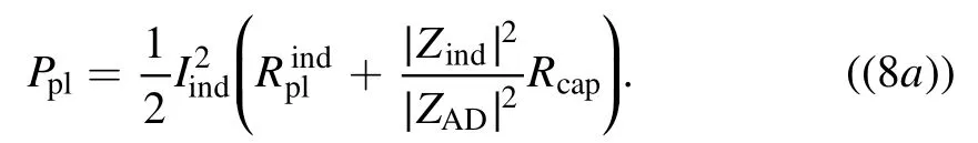
Then we obtain:
We see that the ratio Pind/Pcapdepends on the impedances of the inductive and capacitive channels as well as on the active and equivalent plasma resistances.The mentioned values are the functions of the external parameters of the discharge as well as of its internal parameters i.e.electron density and temperature,argon pressure.On the basis of numerical simulation,it was shown in [14]that electron density in the hybrid discharge depends on the DС potential drop VDCbetween the electrode of the capacitive channel and plasma.It is known that VDCis determined by the RF voltage applied to the electrodes[21].This fact motivated the detailed study of the dependences of the RF voltage between points A and D,C and D on the power RF generator power Pgen,separating capacitor value Csepand argon pressure.
4.2.RF voltage applied to electrodes
Figure 8 shows the dependences of the RF voltage between points A and D,C and D on Pgenmeasured at different values of Csep.When the power of the RF generator is increased,the voltage VAD,i.e.voltage applied to the inductive and capacitive discharge channels also increases.We note that at small RF generator power when the contribution of the capacitive channel to RF power input is large,the growth rate of VADis higher than that in the case when the inductive channel is dominant.In general,the voltage VADincreases with the growth of the RF generator power and decreases with the growth of Csep.
The dependences of the voltage VCDapplied to the capacitor plates,which are in direct contact with the plasma,are shown on figure 8(b).As can be seen,if Csepis less or equal to 50 pF the voltage VCDfirst increases with Pgen,and then practically does not change its value.In the whole considered range of Pgenand Csepthe VCDvalues are significantly lower than VAD.The said effect is observed at all considered pressures (see figure 9).
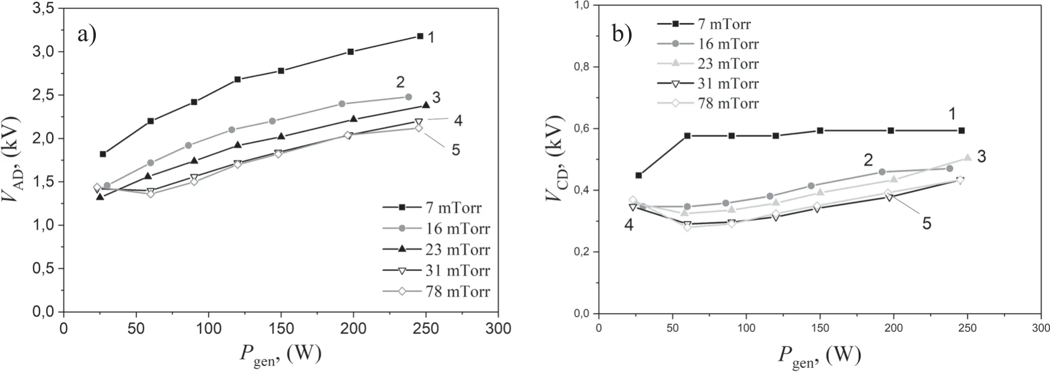
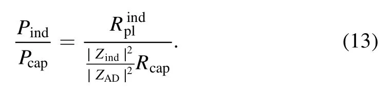
Figure 9.RF voltage between points A and D (a),between points C and D (b) versus RF generator power at different argon pressures p.Hybrid discharge.Csep=13 pF;(1) p=7 mTorr,(2) p=16 mTorr,(3) p=23 mTorr,(4) p=31 mTorr,(5) p=78 mTorr.
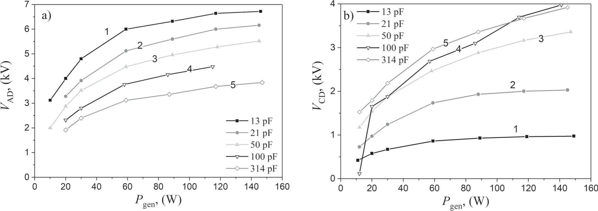
Figure 10.RF voltage between points A and D (a),between points C and D (b) versus RF generator power in case of the pure capacitive discharge.Argon pressure is 23 mTorr;(1) Csep=13 pF,(2) Csep=21 pF,(3) Csep=50 pF,(4) Csep=100 pF,(5) Csep=314 pF.
The effect of VCDdecrease can be observed in the pure capacitive discharge too (see figure 10).However,both VADand VCDvalues in the capacitive discharge are much higher than that in the hybrid one.At Csep=314 pF in the capacitive discharge two voltage amplitudes VADand VCDare nearly equal.
In order to explain the observed dependence VCDon Pgen,let us consider the equivalent diagram of the discharge (see figure 4).The capacitive channel of the hybrid discharge can be considered as a voltage divider between points AC and CD.In the case if
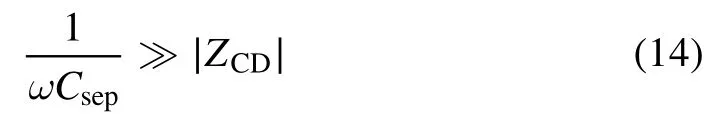
the voltage VCDis much smaller than the voltage VAD,i.e.VCD? VAD.In the opposite case the voltage VCDis close to VAD,VCD≈ VAD.Here ω is the working frequency,is ZCDthe impedance of the electric circuit between points C and D.
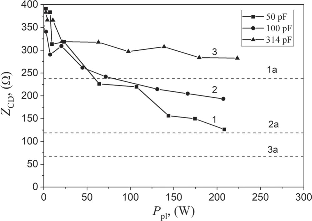
Figure 11.Dependence of the absolute value of the impedance ZCD on the RF generator power.Argon at a pressure of 7 mTorr;(1)Csep=50 pF,(2) Csep=100 pF,(3) Csep=314 pF.Dashed lines represent the impedance of the separating capacitors.(1a)Csep=50 pF,(2a) Csep=100 pF,(3a) Csep=314 pF.
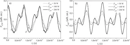
Figure 12.Time dependences of VCD (constant displacement excluded) (a) and Icap (b) with Csep=21 pF.Argon at a pressure of 7 mTorr.(1) Pgen=50 W,(2) Pgen=100 W,(3) Pgen=200 W.

Figure 13.Spectra of (a) RF voltage VCD at the discharge capacitor plates and (b) current Icap flowing through the capacitive channel.Сsep=27 pF,argon at a pressure of 7 mTorr;(1)Pgen=50 W,(2)Pgen=100 W,(3)Pgen=200 W.The numbers I,II and III indicate the first,second and third harmonics.All curves were normalized by the same base value.
Figure 11 shows the experimental dependence of the absolute value of the impedance of the capacitive channel ZСD=VСD/Icapon RF generator power determined for several values of separating capacitor.The ZСDvalues increase with increase of separating capacitance.The comparison of ZСDwith theωC1sepvalues explains the observed reduction of VСDwith decreasing Csep.In case of pure capacitive discharge,it comes out that ∣ZCD∣ >1ωCsepat all considered Csep.The impedance of the inductive channel in the all considered cases was close toωLant.
The impedance of the inductive channel within experimental errors was close to the impedance of antenna in all considered cases.
One more interesting feature that has been observed in experiments.In the case of separating capacitances below or equal to 27 pF nonharmonious variations of VCDand Icapare observed.Typical curves are shown on figure 12.Figure 13 shows the spectra of the RF voltage VCDand current Icapflowing through the capacitive channel.One can see that VCDand Icapdependences on frequency are substantially inharmonious.The spectra represented on figure 13 were obtained by FFT of the measured time dependences of the voltage and current.Note that the time dependences were measured over a limited time interval,so some digital noise can be seen on the graphs.
It is known [21–23]that higher harmonics of the RF generator voltage are generated in the capacitive discharge due to the nonlinear properties of electrode sheaths.We can see from the equivalent circuit of the discharge that the voltage VCDon the discharge capacitor plates is the difference between voltage VAD,a sine wave,and the voltage drop on the separating capacitor,which contains the higher harmonics due to the nonlinearity of the sheath that is accompanied by a nonharmonious behavior of Icap.As a result,a complicated voltage signal appears on the discharge capacitor plates,which,in turn,increases the nonharmonicity of Icap.Measurements showed that the second and third harmonics of voltage and current increase with increasing Pgenand decreasing Сsep.At separating capacitance Сsep> 27 pF,the deposition of higher harmonics substantially decreases.This conclusion is confirmed by the figure 14 where the ratio of the second and first harmonics is represented in dependence on RF power for different values of separating capacitors.The situation with the ratio of the third and first harmonics is similar.Thus,an interesting situation is observed in the hybrid discharge.At low separating capacitances,the inductive channel of the discharge is maintained by the main RF generator frequency,while the capacitive channel is maintained by a combination of its higher harmonics.
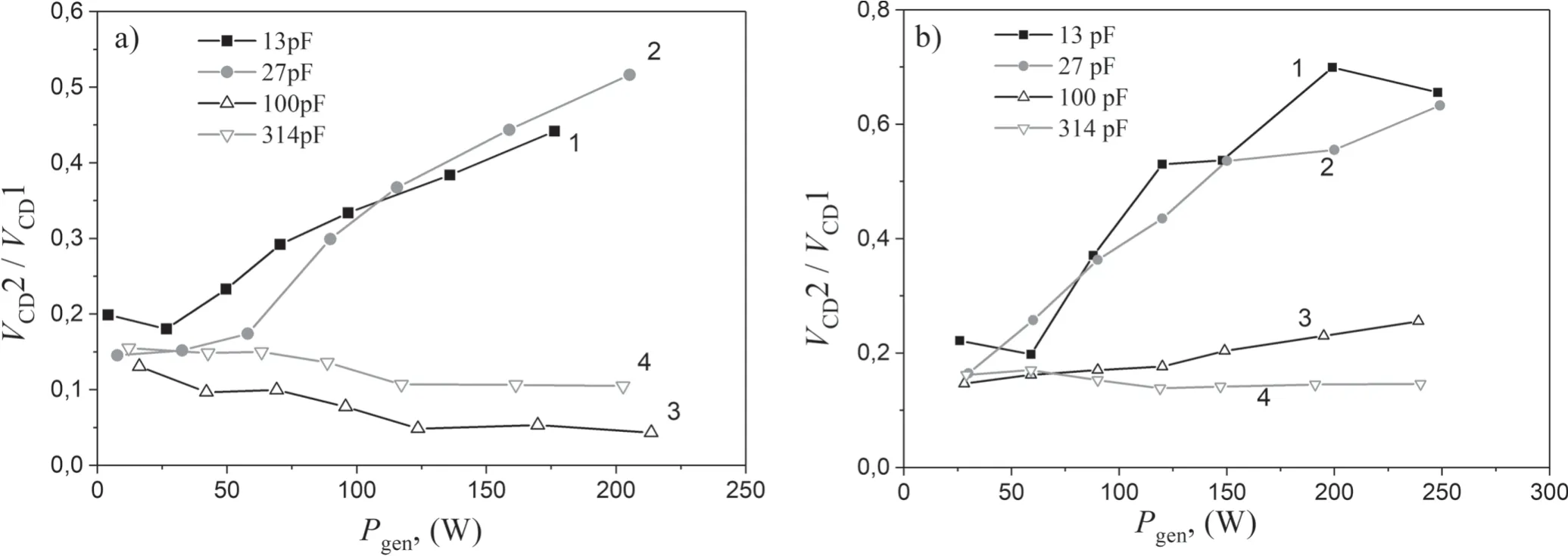
Figure 14.The amplitudes of the second and first harmonics of the RF voltage VCD versus the RF generator power.Argon at a pressure of 7 mTorr (a) and 78 mTorr (b);(1) Csep=13 pF,(2) Csep=27 pF,(3) Csep=100 pF,(4) Csep=314 pF.

Figure 15.Dependence of electron density(a)and electron temperature(b)determined from the inclination of the semilog probe curve near plasma potential on the RF generator power.Argon at a pressure of 7 mTorr:(1)Сsep=13 pF,(2)Сsep=27 pF,(3)Сsep=50 pF;argon at pressure of 20 mTorr:(4) Сsep=13 pF;argon at a pressure of 78 mTorr:(5) Сsep=13 pF.The cylindrical probe made of tungsten wire 0.3 mm in diameter and 5 mm in length was used in the present work.The probe was located in the central section of the plasma source at its axis.
4.3.Plasma parameters
Plasma parameters were measured with the help of cylindrical probe made of tungsten wire 0.3 mm in diameter and 5 mm in length.It was located in the central section of the plasma source at its axis.The dependences of electron density and electron temperature Теdetermined from the inclination of the semilog probe curve near plasma potential on the power of the RF generator are shown on figure 15.Variation of the main plasma parameters is consistent with the change of the RF generator power and voltage VCDapplied to the electrodes of capacitive channel.At small Pgen,where Pcap/Pgenis high,the electron density is low and electron temperature is high.The decrease of Pcap/Pgenis followed by increase of neand drop of Te.At Pgen> 100 W where Pcap/Pgenand VCDare nearly constant the electron temperature does not change within experimental error and weakly depends on the Csep.On the contrary the electron density follows the growth of Pgenin the whole considered range of Pgenand falls with the increase of Csepthat is accompanied by the rise of Pcap/Pgenand VCD.It was shown in [14]that the greater is the potential drop the lower is the electron density because of the increase of the power losses due to the acceleration of ions in the near electrodes sheaths towards the electrodes.The increase of the argon pressure leads to the increase of plasma density and decrease of electron temperature.
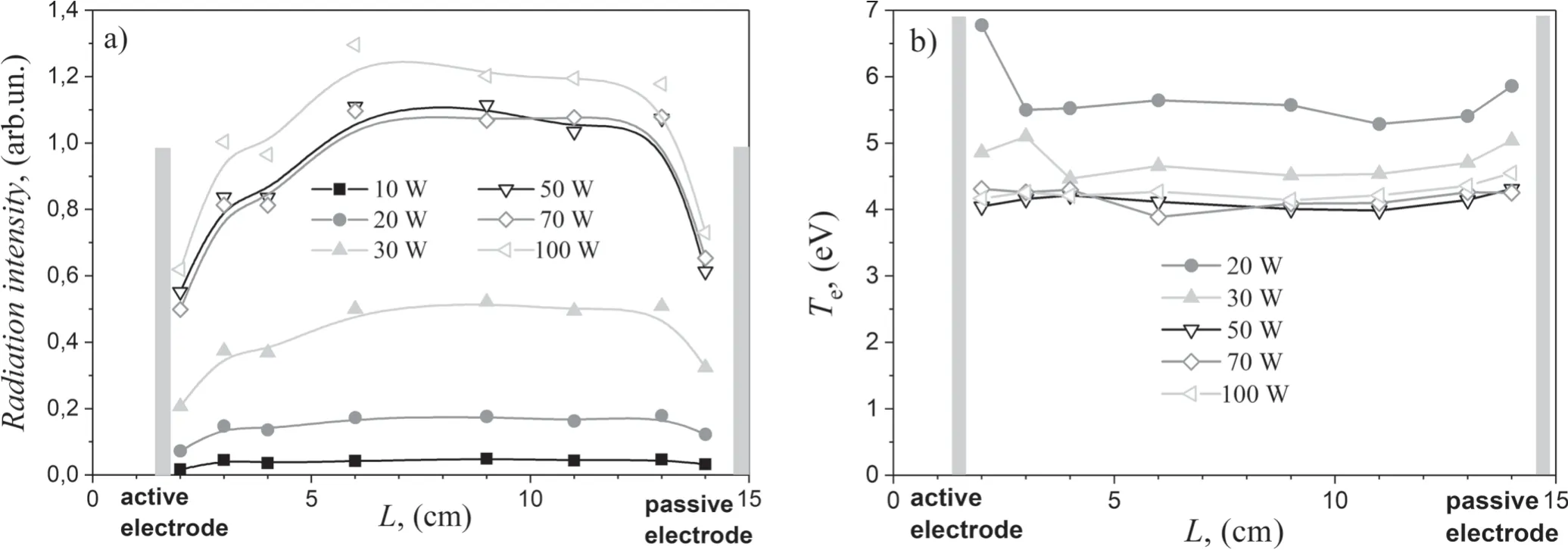
Figure 16.Axial distributions of (a) plasma radiation intensity and (b) effective temperature of fast electrons calculated from the ratio of spectral lines intensities.Сsep=20 pF.Argon pressure is 7 mTorr.
Figure 16(a) shows the axial distribution of the argon plasma radiation at a wavelength of 4198 ?.It is seen that in the main discharge volume,the plasma is homogenous.The decrease in plasma radiation intensity in the electrode region is caused in part by the decrease in the plasma volume whose radiation is gathered by the entrance slit of the monochromator.Increasing RF generator power causes increasing plasma radiation.The sharp increase of the intensity takes place in the region of the RF generator power 20–50 W.This sharp increase can be attributed to the significant decrease in Pcap/Pindand the transition of the discharge from E- to H-mode.It was shown in[14]that one of the most important factors that controlled electron density at a given Pplwas the value of the DC potential drop in the near electrode sheaths.This value increases with the increase of Pcap/Pind.The larger the potential drop,the lower electron density.This is the result of the power losses at the electrodes of the capacitive channel due to the flow of the ions accelerated in the near electrode sheaths [14].
Figure 16(b) shows the spatial distribution of the effective temperature of fast electrons Те*determined from the ratio the intensities of spectral lines Ar I 4198 ? and Ar I 4200 ?.It is seen that increasing the RF generator power Pgencauses the decrease in the effective electron temperature.A sharp rise of Те*is observed at values of Pgenbelow 30 W,while at higher Pgen,the effective temperature of fast electrons remains almost constant.
It should be noted that at Pgen≤ 30 W,the effective electron temperature of fast electrons increases near both the active and passive electrodes.This is caused by the formation of electrode space charge sheaths,where fast electron beams originate[23].At generator power Pgen> 30 W,the situation changes.The effective temperature of fast electrons only increases near the passive electrode.Near the active electrode,Те*is close to the temperature of fast electrons in the main plasma volume.This effect continues until the separating capacitance reaches 50 pF.To understand the reason of the disappearance of the maximum of Те*near the active electrode the plasma potential and the self-bias of the active electrode have been measured.
4.4.Plasma potential and the self-bias of the active electrode
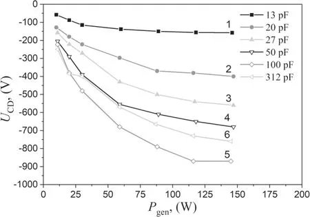
Figure 17.Dependence of the DC potential difference between the capacitive RF discharge electrodes on the RF generator power in pure capacitive discharge.Argon at a pressure of 7 mTorr;(1)Сsep=13 pF,(2) Сsep=20 pF,(3) Сsep=27 pF,(4) Сsep=50 pF,(5) Сsep=100 pF,(6) Сsep=312 pF.
It is known [21–23]that in the capacitive discharge in the presence of a separating capacitor breaking the direct current between the electrodes,a DC negative self-bias usually forms on the active electrode relative to the passive electrode.In this work,the dependence of the DC active electrode bias UCDon the RF generator power was measured in experiments with separating capacitances equal to those used during the studies of the hybrid RF discharge.These measurements showed that UCDbehavior agrees with modern views of the physical processes taking place in the capacitive RF discharge (see figure 17).
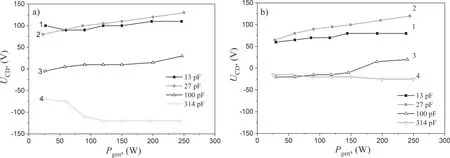
Figure 18.Dependence of the DC potential difference between the active and passive electrodes of the hybrid RF discharge on the RF generator power in argon at pressures of (a) 7 mTorr and (b) 16 mTorr.
A different picture is observed when studying the selfbias of the active electrode in experiments with the hybrid RF discharge (see figure 18).At a separating capacitance of 314 pF,the self-bias of the active electrode is negative,similar to the capacitive discharge,yet the absolute values of the DC potential are appreciably lower than in the capacitive discharge.At a separating capacitance of 100 pF,the self-bias of the active electrode is only negative at low values of RF power coupled to the plasma.As Pgenincreases,the DC potential of the active electrode passes zero and becomes positive.At even lower values of the separating capacitance,the DC potential of the active electrode is positive at all studied values of Pgen.Analysis carried out using the formulae obtained in [21–23]shows that the observed effect is possible under condition that the capacitance of the active electrode sheath is greater than the capacitance of the passive electrode sheath.The latter is true under condition that the active electrode sheath thickness is less than the passive electrode sheath thickness.It bears reminding that spectral measurements showed that the effective temperature of fast electrons,i.e.the ratio of intensities of ion and atomic lines at Csep≤ 50 pF,increases only near the passive electrode,which indicates that the passive electrode sheath consists of positive space charge.Near the active electrodeTe*did not increase within our chosen spatial resolution.This indicates that the sheath thickness near the active electrode is small and implicitly confirms the probe method results.
Together with measurements of the DC self-bias of the active electrode,the floating potential of the probe was also measured in the capacitive and hybrid discharges.In the capacitive discharge,as expected,the floating potential is positive relative to both the passive and active electrodes,and the potential difference between the probe and the active electrode can be substantially higher.The case of the hybrid discharge is different.The floating potential of the probe is positive relative to the active electrode only at Csep≥ 100 pF.At lower separating capacitances increasing the RF power coupled to the plasma leads to the floating plasma potential becoming lower than the active electrode potential.
4.5.Parameters of the space charge sheath near the passive electrode
Probe and spectral studies of the hybrid RF discharge showed that a space charge sheath forms near the passive electrode.Let us estimate the thickness of this sheath,equating the ion current on the electrode calculated using the Bohm formula[21,22]with the current calculated using the Child–Langmuir law [21,22]:
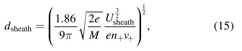
where n+is the ion density,v+=is the ion velocity,М is the ion mass,dsheathis the sheath thickness,and Usheathis the voltage drop in the sheath.
Figure 19 shows the dependence of the sheath thickness on the RF generator power at different separating capacitances and argon pressures.It is seen that the sheath thickness increases with increasing separating capacitance and decreases with increasing RF generator power and argon pressure.
4.6.Comparison of the hybrid,capacitive,and inductive RF discharge properties
The hybrid RF discharge is a modification of the known forms of the RF discharge.Let us compare the properties of hybrid,capacitive,and inductive RF discharges.The simplest approach is studying the spectral composition and plasma radiation intensity of the above-mentioned discharge modifications.
Figure 20 shows the spatial distribution of the ratio of ion 4765 ? and atomic 4200 ? argon line intensities η measured in the different modifications of the RF discharge.The excitation potentials of the lines 4765 and 4200 ? are 33 and 15 eV.The electron energies corresponding to the maximum of excitation cross sections of the ionic and atomic lines are 78 and 23 eV respectively.Thus,the ratio of the two lines is sensitive to the presence of fast electrons.As expected,η reaches maximum values in the capacitive discharge where an excess of fast electrons formed in the electrode space charge sheath is observed [21–23].The mechanism of fast electron formation manifests in the increase of the ratio η near the electrode held under the RF voltage.
The lowest values of η are characteristic of the inductive RF discharge,where a deficit of fast electrons is observed[13],caused by inelastic electron collisions with argon atoms.
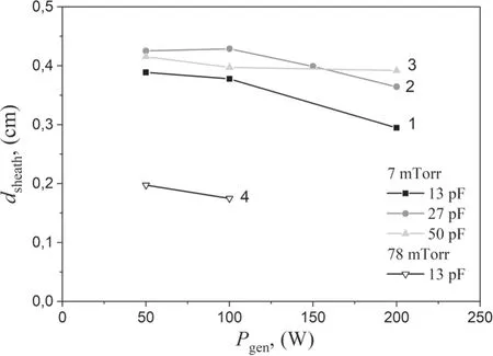
Figure 19.Dependence of the sheath thickness near the passive electrode on the RF generator power.Hybrid discharge.Argon at a pressure of 7 mTorr:(1) Сsep=13 pF,(2) Сsep=27 pF,(3)Сsep=50 pF;argon at a pressure of 78 mTorr:(4) Сsep=13 pF.
The values of η in the hybrid discharge are between its values characteristic of the inductive and capacitive RF discharge.In the case of a separating capacitance of 13 pF,the increase in the intensity ratio of lines 4765 ? (Ar II) and 4200 ?(Ar I),which characterizes increasing of fast electrons effective temperature,is observed only near the passive electrode,while near the active electrode,the values of η are close to those in the main discharge volume.In the case of a separating capacitance of 300 pF,the values of η increase near both the passive and active electrodes,which indicates that space charge sheaths form near both electrodes.
Increasing the separating capacitance Csep,on one hand,increases the number of fast electrons,and on the other hand,is accompanied by decreasing the intensity of the plasma glow.
The results presented in figure 20 demonstrate that the plasma parameters of the hybrid RF discharge are in the range between the plasma parameters of the inductive and capacitive RF discharges,and that changing the external circuit parameters in the studied range of separating capacitances allows one to smoothly change the discharge characteristics.This opens a wide range of possibilities to use the hybrid RF discharge as the working medium of technological plasma reactors with smoothly adjustable parameters.
5.Discussion
Let us consider once more equation (11) and analyze the quantities included in the right side of equation (11).The behavior ofRplindRplindin dependence on main internal and external discharge parameters was studied in detail in [24].It was shown that under conditions when RF power absorption mechanism was a collisional one,two values,i.e.electron density and the frequency of electron collisions with neutral atoms νea,definedRplindunder fixed Ppland dimensions of plasma vessel.
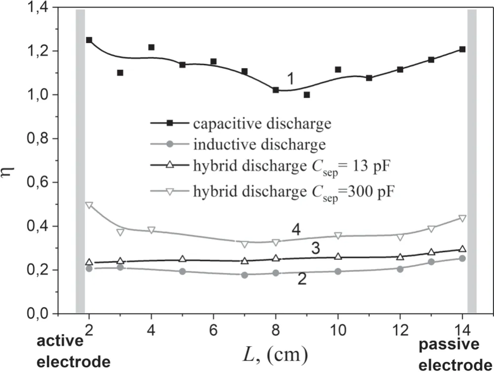
Figure 20.Dependence of the ratio of line intensities Ar II/Ar I(4765–4200 ?)on the distance between the electrodes:(1)capacitive discharge,(2) inductive discharge,(3) hybrid discharge with Сsep=13 pF,(4) hybrid discharge with Сsep=300 pF.Argon pressure is 7 mTorr.
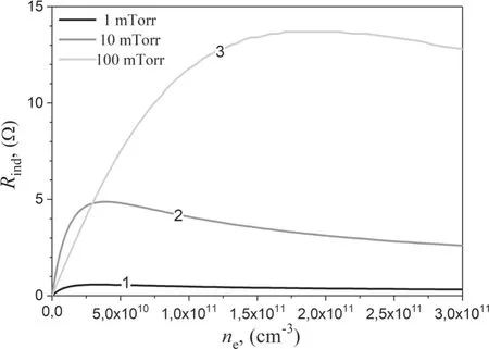
Figure 21.Plasma equivalent resistance versus electron density.Ar pressure:(1)—1 mTorr,(2)—10 mTorr,(3)—100 mTorr.
The calculatedRplindin the present work are presented in the figure 21.The non-monotonous variation ofRplindwith neoccurs due to the competition of two factors,i.e.growth of the number of electrons participating in power absorption with increase of neand decrease of this number due to the decrease of skin depth [24].The pressure and νeagrowth first lead to increase of theRplindabsolute values without significant change of theRplindmaximum positionn,e* thenne* shifts towards higher values of electron density.
In the case when collisional mechanism of power absorption dominates,the plasma active resistance Rcapalso depends on the electron density and frequency of electron collisions.Contrary toRplind,Rcapdecreases with increase of ne,while the growth of νealeads to the rise of Rcapsimilar toRplind.
Experiments showed that Zindwas fixed and determined by the antenna inductance.The impedance of the capacitive channel ZADis the function of the plasma active resistance and impedances of separating and sheath capacitances.The important thing is that the impedance of the capacitive channel is bounded from below by the impedance of separating capacitor.
Having in mind the above said and regarding the figure 3 it is easy to understand the patterns of power coupling through different discharge channels.At low values of Ppl,the plasma density is low,the equivalent resistance which is included in the inductive branch of the equivalent scheme is also low[15],while the active plasma resistance included in the capacitive branch is high.Under such conditions the RF power coupled to the discharge through the capacitive channel can be significant.The definite value Pind/Pcapdepends on the ratio of channels impedances as well as resistancesRplindand Rcap.
Under increase of Pgenthe electron density goes up,as a consequence the plasma equivalent resistanceRplindalso grows.At the same time plasma active resistance and impedance of electrode sheaths reduce.As a result,the fraction of power coupled to the discharge through the capacitive channel decreases.
In [14]it was shown that one of the most important factors that controlled electron density at a given Pplwas the value of the DC potential drop in the near electrode sheaths.The larger the potential drop,the lower electron density.As a consequence,the equivalent plasma resistanceRplinddecreases,that causes the reduction of Pindand increase of the power value released in the capacitive channel.Under such conditions,the properties of the hybrid discharge tend to that of the pure capacitive one.In pure capacitive discharge the values of VСDare higher than in the hybrid one.That is the reason why at the same RF generator power the electron density and plasma radiation intensity are lower.Thus,the change of the separating capacitance value makes it possible to control the hybrid discharge parameters.
6.Conclusions
Experimental studies of the hybrid RF discharge showed that at low RF generator power,the power is mostly coupled to the discharge through the capacitive channel.Increasing the RF generator power increases the power coupled through the inductive channel,the electron density and the current flowing through the capacitive channel.This leads to increasing voltage drop on the separating capacitor and partial cutoff of the capacitive channel.Experiments showed that at separating capacitance of 50 pF and below,the self-bias of the loaded electrode becomes positive,which indicates that the thickness of the sheath near the loaded electrode decreases relative to the thickness of the sheath near the grounded electrode.At separating capacitance less than 50 pF,intense generation of higher harmonics of the RF generator voltage takes place in the capacitive discharge channel.Increasing the separating capacitance leads to decreasing the discharge operating voltage,increasing voltage drop in the electrode sheaths,decreasing electron density due to enhancement of energy losses caused by the ion flow to the electrodes,increasing sheath thickness and decrease in its capacitance,increasing active plasma resistance and the fraction of RF power coupled to the discharge through the capacitive channel.The hybrid RF discharge parameters fill the region between the plasma parameters of the inductive and capacitive RF discharges,and changing the parameters of its external circuit allows one to smoothly change the discharge parameters.
 Plasma Science and Technology2020年5期
- Plasma Science and Technology的其它文章
- Vickers hardness change of the Chinese low-activation ferritic/martensitic steel CLF-1 irradiated with high-energy heavy ions
- Comparison of discharge characteristics and methylene blue degradation through a direct-current excited plasma jet with air and oxygen used as working gases
- Evaluation of influence of cold atmospheric pressure argon plasma operating parameters on degradation of aqueous solution of Reactive Blue 198 (RB-198)
- Plasma-induced graft polymerization on the surface of aramid fabrics with improved omniphobicity and washing durability
- Plasma-assisted abatement of SF6 in a packed bed plasma reactor:understanding the effect of gas composition
- The far-field plasma characterization in a 600W Hall thruster plume by laser-induced fluorescence