
Numerical estimation of bank-propeller-hull interaction effect on ship manoeuvring using CFD method*
2017-03-09 09:09:54KaidiSmaouiSergent
水動(dòng)力學(xué)研究與進(jìn)展 B輯 2017年1期
S. Kaidi, H. Smaoui, P. Sergent
1.CEREMA-DtecEMF, 60280 Margny-lès-Compiègne, France
2.Sorbonne universités, Université de technologie de Compiègne, laboratoire Roberval, 60203 Compiègne cedex, France, E-mail: sami.kaidi@cerema.fr
(Received November 9, 2015, Revised May 11, 2016)
Numerical estimation of bank-propeller-hull interaction effect on ship manoeuvring using CFD method*
S. Kaidi1,2, H. Smaoui1,2, P. Sergent1
1.CEREMA-DtecEMF, 60280 Margny-lès-Compiègne, France
2.Sorbonne universités, Université de technologie de Compiègne, laboratoire Roberval, 60203 Compiègne cedex, France, E-mail: sami.kaidi@cerema.fr
(Received November 9, 2015, Revised May 11, 2016)
This paper presents a numerical investigation of ship manoeuvring under the combined effect of bank and propeller. The incompressible turbulent flow with free surface around the self-propelled hull form is simulated using a commercial CFD software (ANSYS-FLUENT). In order to estimate the influence of the bank-propeller effect on the hydrodynamic forces acting on the ship, volume forces representing the propeller are added to Navier-Stokes equations. The numerical simulations are carried out using the equivalent of experiment conditions. The validation of the CFD model is performed by comparing the numerical results to the available experimental data. For this investigation, the impact of Ship-Bank distance and ship speed on the bank effect are tested with and without propeller. An additional parameter concerning the advance ratio of the propeller is also tested.
Viscous fluid flow simulation (CFD), bank effect, bank-propeller-hull interaction, hydrodynamic forces estimations, advance ratio
Introduction
The transport by inland waterways is considered as an alternative to rail and road transport. Over these years this mode of transport has seen a significant increase due to the encouragement of governments to the exploitation of waterways. This is, on the one hand, to relieve the other modes of transport and, on the other hand, for its ecological quality.
Navigation in inland waterways faces a major risk which concerns mainly accidents due to ship controllability. In contrast to the maritime navigation, the waterways navigation environment plays an important role in the ship manoeuvrability (channel geometry, water depth, bank distance,…), therefore, it is important to study the manoeuvrability in confined water in order to offer proposals concerning a development and security.
In the present work, we focus on the study of bankeffect. Norrbin[1], was the first to work on Ship-bank interaction. The conclusion of shis experiment has shown a significant impact of the banks on the trajectory of ships. His study was improved later by Ch'ng et al.[2]by taking into account new parameters, such as bank slope, hull form, water depth, bank height and ship speed.
Recently, Duffy[3,4]and Vantorre et al.[5]conducted a series of experimental tests and carried out a study in the influence of some parameters such as water depth, distance to the bank, bank slope, bank height and the forward speed on hydrodynamic force and moment by using a Captive Model Test model. The results of their works showed that the sway force and yaw moment are linearly influenced by the distance to the bank. Few years after, an empirical mathematical formula was proposed by Lataire et al.[6]to calculate the bank-ship interaction forces as a function of the bank geometry, ship speed and propulsion system.
With the fast development of the computer technology and the commercial CFD software, the CFD method has interested the inland community. This method is used mostly and it has proved its ability to predict the ship manoeuvring hydrodynamic forces inmedium deep waters.
Miao et al.[7]used a potential flow method for calculating the lateral force and yaw moment for a ship sailing in a rectangular channel. Lo et al.[8]performed a series of simulations to estimate the bank effect of a container ship taking into consideration the viscous action, by using the commercial CFD software based on Navier-Stokes equations. The temporal variation of yaw angle and sway force by varying the ship speed and the distance to the bank were also discussed. Recently, Wang et al.[9]studied the bank effect for a series of hull for several water depth-ship draught ratios and ship-bank distance, using a CFD method to estimate the viscous force better. Ma and Zhou[10]studied the hydrodynamic interaction among hull, rudder and bank. The verification and validation of this method was carried out by Zou et al.[11]. This method was used later to simulate different channel geometries by Zou and Larsson[12].
In this investigation, a preliminary study is presented to predict the combined effect of bank-propeller on the ship manoeuvrability. The theme of this work is the use of viscous CFD model to estimate the different hydrodynamic forces acting on the hull with and without propeller, taking into consideration the influence of ship position on bank, ship speed and the advance ratio of the propeller. The viscous CFD model is updated by adding additional volume forces to represent the propeller action.
1. Problem formulation
1.1Governing equations
The governing equations for mass and momentum conservation are the Reynolds averaged Navier-Stokes (RANS) equations for incompressible flow, by using the Einstein notation these equations are given as bellow:

The Reynolds stresses introduce new variables, which makes the equation system Eqs.(1)-(2) not closed. To close and solve this system, several complementary mathematical models with additional equations are proposed, these models are called turbulence models. In the present work, among the various turbulence model proposed by Fluent, the implicit Menter Shear Stress Transport (SST)k-ωmodel[13]was chosen for its robustness and stability. The (SST)k-ωequations are shown as follows:
GkandGωdenote the generation of turbulent kinetic energy due to mean velocity gradients andω,YkandYωrepresent the turbulence dissipation ofkandω,Dωis the cross-diffusion term,SkandSωare user-defined source terms.GkandGωexpress the active diffusivity ofkandω.
1.2CFD Solver
In this work, the incompressible free surface flow around the ship hull is studied using the commercial RANS code “Ansys-Fluent? based on the finite volume method. The pseudo transient pressure-based coupled algorithm is adopted to compute the pressurevelocity coupling, the (PRESTO) interpolation method is selected to compute the cell-face pressure.
To capture the free surface in air-water interface, the implicit volume of fluid (VOF) method based on a second order scheme is employed. The VOF is an Eulerian method particularly used for flows with deformed interfaces. Using this approach the air-water interface can be tracked in a fixed grid by solving the continuity equation of the volume fraction (Eq.(7)).
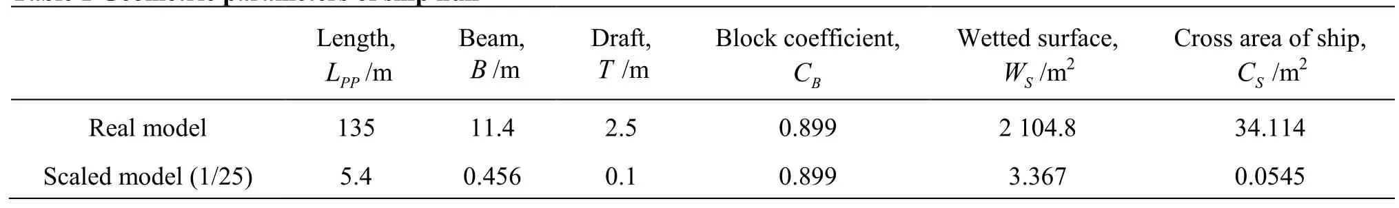
Table 1 Geometric parameters of ship hull
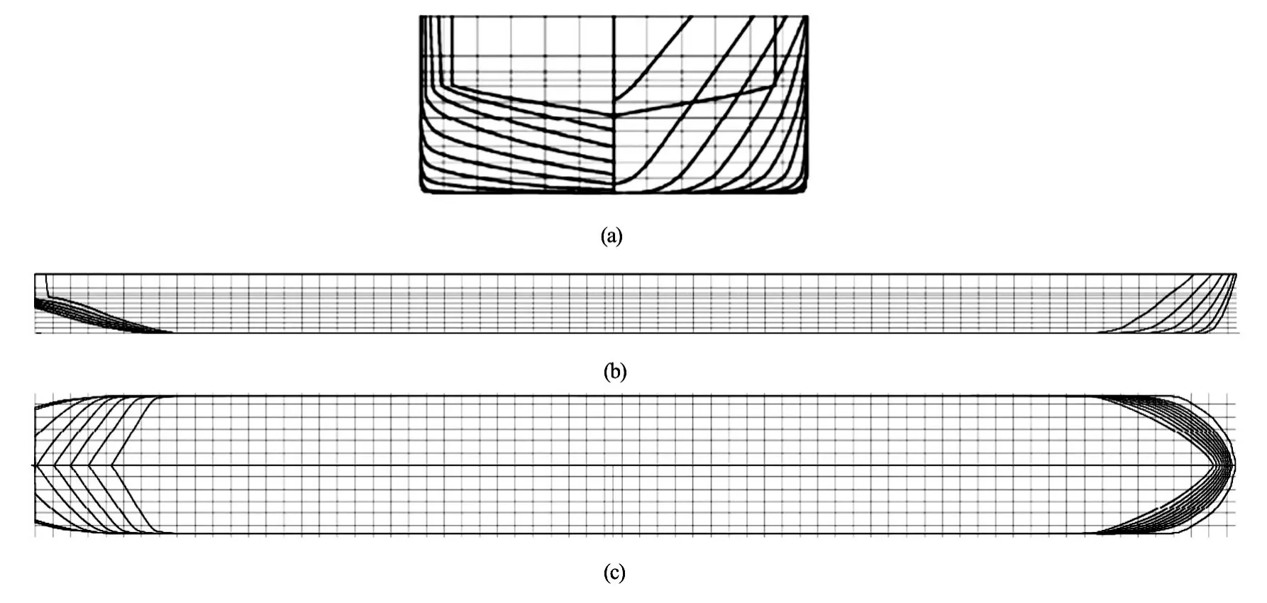
Fig.1 Lines plan of the self-propelled ship
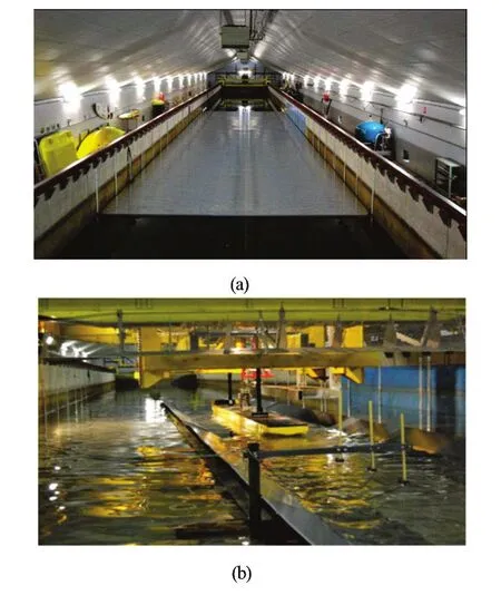
Fig.2 (Color online) Illustration of the test tank
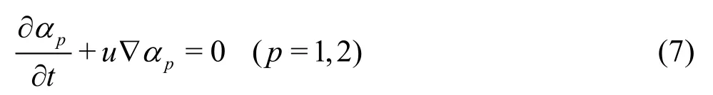
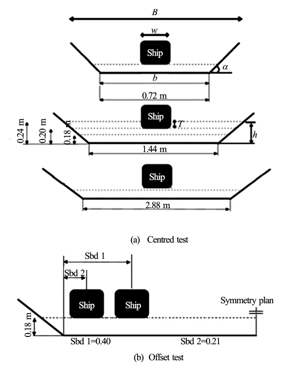
Fig.3 Channel geometries
αpdenotes the volume fraction of thept hfluid, and
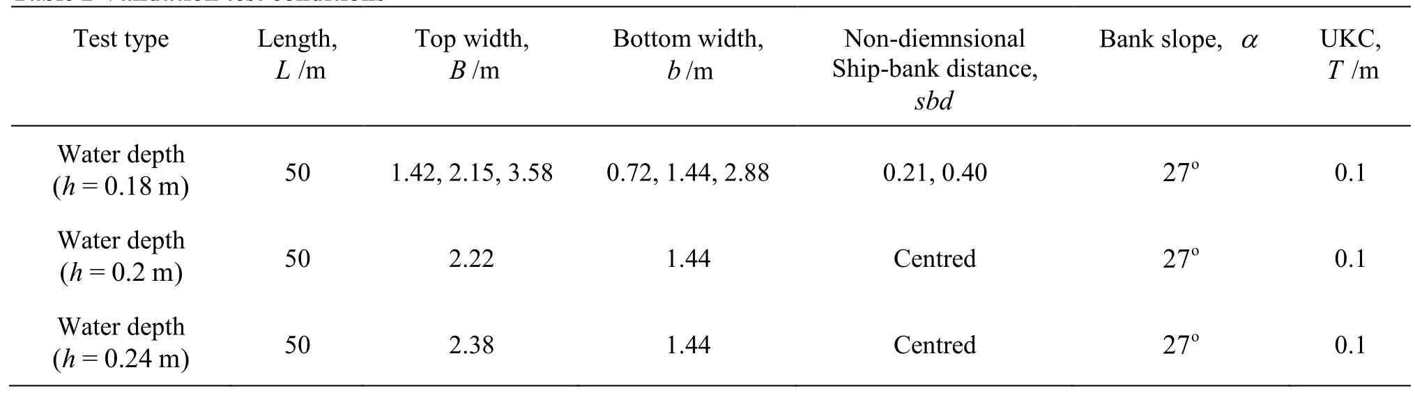
Table 2 Validation test conditions
1.3Ship hull
In this investigation, the hull form of the self-propelled container ship (135 m of length and 1 140 m of width) is selected for both test cases, experimental and CFD. No rudder and no propeller are included for the validation tests. The propeller will be included only in the last section of this work. The ship hull geometry for tested model is presented on the scale of 1/25. Table 1 and Fig.1 show the main characteristics and the body lines of the hull form.
2. Presentation of the experimental tests
The tests conducted for this work are realized in the towing tank at the Liege University (Length is 100 m, width is 6 m and depth is 3.5 m, see Fig.2). Figure 3 and Table 2 present the geometrical characteristics for all the tested configurations (three channel widths, three under keel clearance and two ship-bank distances).
The test device consists of a towing carriage that tows the ship model with a speed which can reach 5 m/s and a balance to measure the forces and moments acting on the ship model.
To test the effect of the bank, independent panels inclined 27owere placed one beside the other (Fig.4).
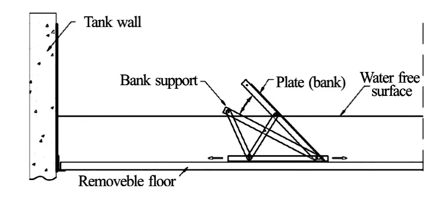
Fig.4 Middle section of the tank with mobile bank
3. Validation of numerical model
To validate the CFD model, the numerical results of the ship resistance were compared with those measured in towing tank. Seven geometrical configurations are simulated. Five configurations (three water depths and three bottom widths) with a ship positioned at the centre of the channel (see Fig.3(a)) and one geometrical configuration with two ship-bank distances (see Fig.3(b)). For each configuration, different ship speeds varying between 0.222 m/s and 0.575 m/s (between 4 km/h and 10 km/h in real scale) are tested. Due to the symmetry of the domain studied for the centred ship cases, only half of the domain is considered and meshed. However, for the coming other cases, the whole domain is meshed.
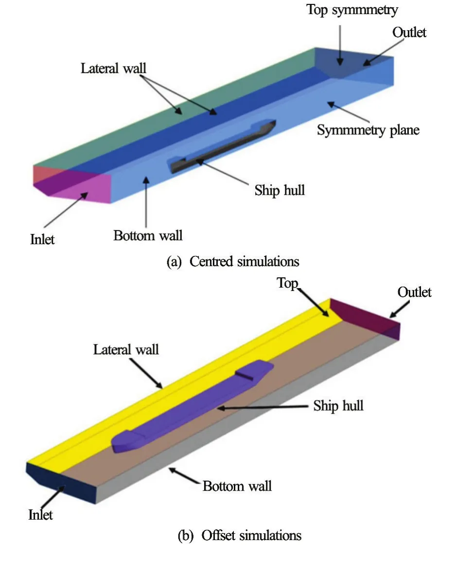
Fig.5 (Color online) Boundary conditions applied
In this investigation, only three most influential forces and moments were examinedX,YandN. The non-dimensional form of these forces and moment are,and, defined as:
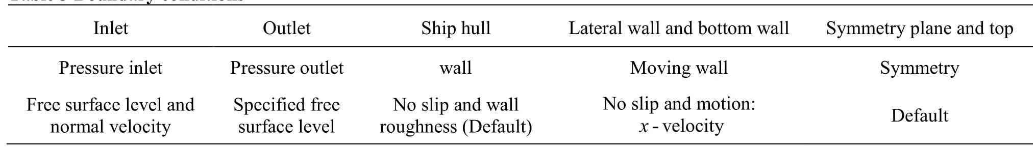
Table 3 Boundary conditions
The non-dimensional ship-bank distance is expressed by the ratio
whereymax=0.8 mrepresents the largest scaled distance tested between the ship and the bank.
3.1Boundary conditions
The following figures show the standard computational domain with all boundary conditions applied for centred ship (only half model is considered, see Fig.5(a)) and offset ship position (whole model is considered, see Fig.5(b)). The boundary conditions shown in the following figures are detailed in Table 3.
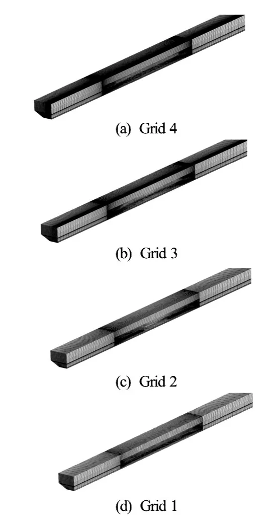
Fig.6 Grids tested
3.2Grid settings
For the validation cases, the domain studied is meshed with a mixed mesh. The region around the ship hull is meshed using non-structured tetrahedral elements, and the rest of the region studied is meshed with structured hexahedral elements.
For an accurate resolution of the viscous flow, the mesh is appropriately refined at the air-water interface to better represent the free surface variation and made near the ship to estimate the hydrodynamic forces (pressure and viscous forces) acting on the hull form more exactly (Fig.6). The mesh quality used for the investigation tests is chosen after a mesh sensitivity analysis. This analysis is based on the test of different mesh qualities varying from 0.76×10⁶to 2.24×10⁶of elements. To perform this sensitivity test, the identical simulation conditions are used for all grid tests. Where, the channel width and the water depth are 1.44 m and 0.18 m respectively (see Fig.5(b)) and the ship speed is 0.45 m/s.
Table 4 shows the evolution of the error between the measured and the computed ship resistance as function of grid quality. The simulations illustrate that the error is stabilized and the numerical results start converging from the Grid 3. The relative errorE= [(Rm?RC)/Rm]is estimated to be 3.1%. All following simulations use the quality of the Grid 3.
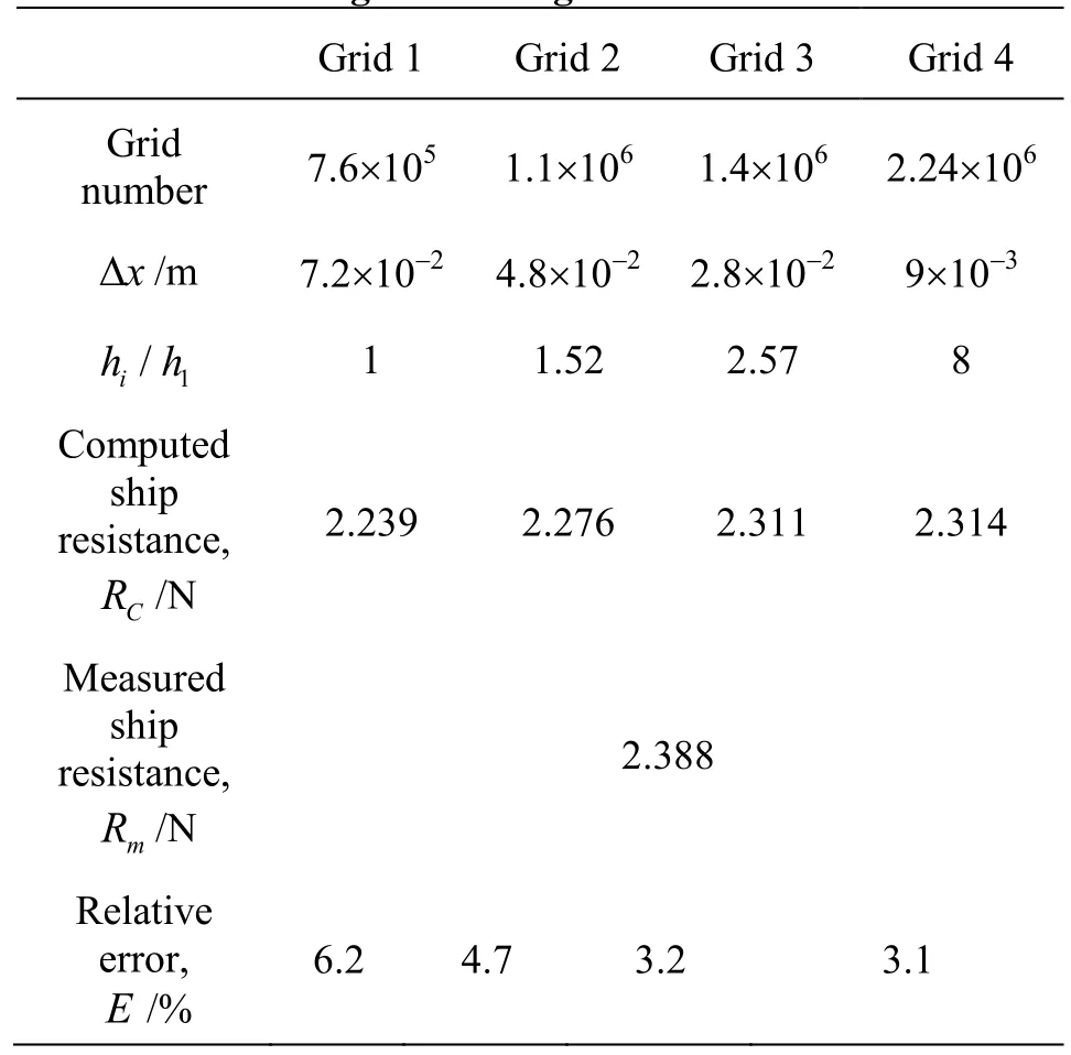
Table 4 Test of the grid convergence
3.3Centered ship results
Figure 7 shows the comparison between the computed and measured ship resistance. By analyzing these graphs, a similar tendency of the both results is noted.
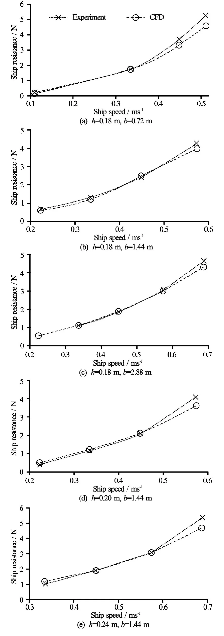
Fig.7 Comparison of the CFD results with measurements
We observe that for all tests, the relative error depends on two parameters, the ship speed and the confinement of the navigation environment. Where the error increases with increase of the ship speed and the blockage factor of the ship “BF? and reduce of the ratio between the water depth and the deep draft (h/T).
Table 5 gives the evolution of the relative error for all cases aforementioned as function of confinement coefficients (BF andh/T). From this table it is clearly seen the influence of the ship speed on the error evolution. For all cases the maximum relative error is reached for the higher value of the ship speed.
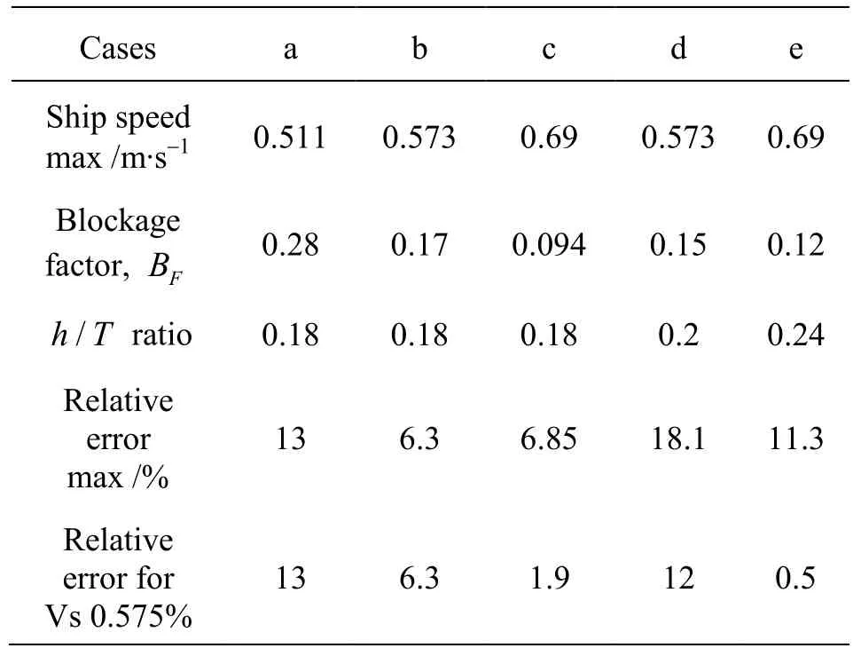
Table 5 Error evolution
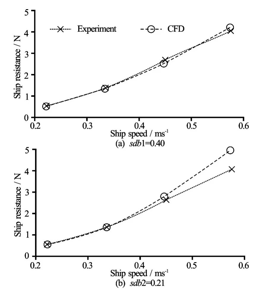
Fig.8 Ship resistance comparison
The influence of the blockage factor on the relative error is clear by comparing Cases a, b and c. For the sameh/Tratio and the highest common ship speed(≈0.511m/s-0.575 m/s)it is observed that the error increases with increas of the blockage factor. The maximum value of this error is 13% noted in theCase a. The comparison of Cases b, d and e can illustrate the influence ofh/Tratio on the error variation. The relative error decreases with increase of the ratioh/T. Except for Case d, where the relative error at high ship speed is very large (18.1%) due to an over-estimation of the measured ship resistance.
The relative error between the computed and measured ship resistance especially at high ship speed, can be explained by the use of some simplifying assumptions. Among the assumptions that can influence the numerical results is the neglect of the ship squat. At a high speed in a restricted channel, the ship sinks significantly in water and usually causes an additional resistance. Hence, ignoring the modelling of this phenomenon, it generates a pronounced difference between the two results.
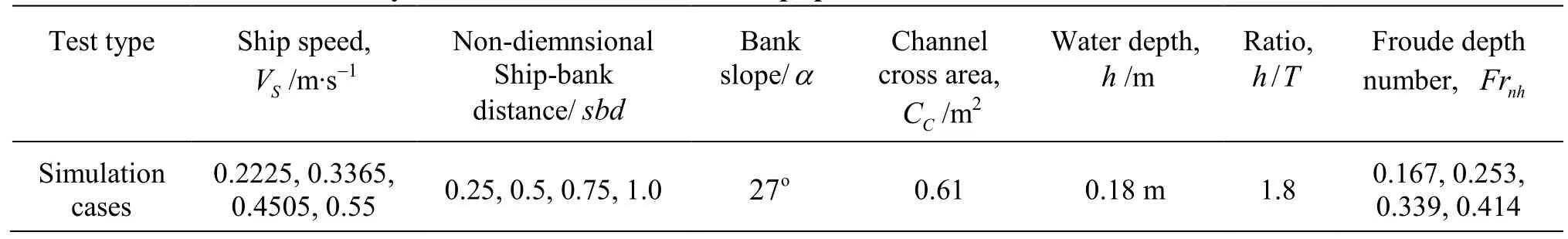
Table 6 Test conditions to study the influence ofsbdand ship speed
3.4Offset ship position results
In this section, additional validation tests are performed to examine the bank effect. This is rendered possible by experimental facilities that use a removable bank. Two offset positions of the ship to the bank (sbd)0.21 and 0.4 (see Fig.2 and Table 2) are tested for four different speeds. Figure 8 presents the comparison between the computed and experimental ship resistance.
From this figure, it is shown that the allure of the computed and measured results is identical. It may also be noted that the ship resistance is well estimated by the CFD model for both ship positions when the ship speed is less than 0.45 m/s. Where relative error achieved maximum at this speed is 5.1% for the first ship position(sbd1=0.40)and 5.6% for the second ship position(sbd2=0.21). For the highest ship speed (0.575 m/s), the relative error is still reasonable for the first case(sbd1=0.40). However, when the ship is closer to the bank(sbd2=0.21)we note a significant error (21%). In this case the measured ship resistance is underestimated and this important gap is due particularly to a technical problem encountered during measurement sessions. When the ship is sailing close to the bank, the pressure forces of the wave crests between the ship and the bank increase and move slightly the independent panels representing the bank, which explain this energy dissipation.
4. Test results
The validated numerical model is used in order to perform a comparative study in the combined effect of the bank and the propeller on the ship maneuverability. This section is divided into two parts: the first part concerns the influence of the ship-bank distance (sbd) and the ship speed, while the second part treats the influence of the propeller system as function of shipbank distance, the ship speed and the propeller advance ratio. For the next simulations, to estimate the forces associated with the bank, we consider only one bank and assume the other bank is far apart thus the numerical model can be simplified by adding a symmetry plane condition.
4.1Tests without propeller
In this first part of results, we study the influence of the ship-bank distance and the ship speed on the effect of the bank. This investigation was carried out by varying the ship speed and the ship-bank distance.
Four positions of the non-dimensional ship-bank distance (sbd)varying between 0.25 and 1 were tested and for each position the ship speed was varied between 0.2225 and 0.55 m/s. Table 6 summarizes the test conditions to simulate the sbd and ship speed influence.
Figure 9 presents the impact of thesbdand the ship speed parameters on the non-dimensional forces acting on the ship (ship resistance, sway force and yaw moment). The results show that hydrodynamic forces are affected by thesbd. These forces increase when the ship is close to the bank and become lower for a largesbd. It’s observedthat the tendency of the hydrodynamic forces as function ofsbdis almost linear, which is in agreement with the experimental results reported by Vantorre et al.[5].
The figures represent also the ship speed impact. For a givensbddistance, the curves show that all hydrodynamic forces acting on the hull increase with increasge of the ship speed, the variation of the ship resistance is proportional to the square of the ship speed. While the sway force and yaw moment are not considered proportional to square of the ship speed.
Comparing the effect of the both parameters (thesbdand the ship speed), the results confirm that the influence of the ship speed on the bank effect dependsstrongly on thesbddistance. Whensbddistance is larger, the influence of ship speed is insignificant, however, when the ship is close to the bank, the ship speed influence increases rapidly and the hydrodynamic forces achieve high values. This is in agreement with the experimental investigation performed by Sian et al.[14]. The 3-D plots (Fig.9) illustrate better the combined influence of thesbdand the ship speed.
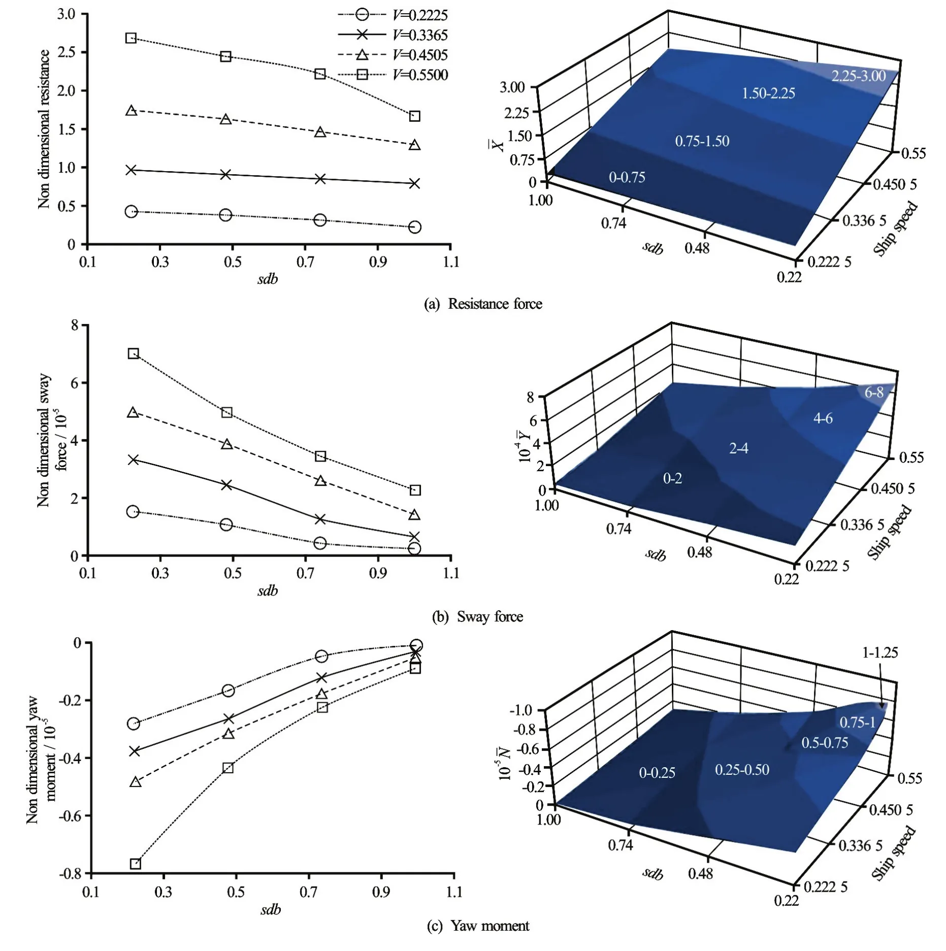
Fig.9 (Color online) Non-dimensional values versussbdfor different ship speed
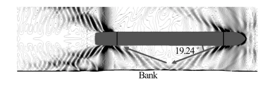
Fig.10 Propagation of ship generated waves
According to the experimental investigation conducted by Duffy[4]the hydrodynamic forces around the ship can be attractive or repulsive. The nature of this interaction depends on a number of factors such as blockage coefficient, Froude depth number and the bank geometry. When the flow velocity between the ship and the bank is faster than that on the other side, the pressure is lower. Hence the lateral force acting on the ship is attractive. The lateral force is considered repulsive, when the blockage and the Froude depth number are higher (h/T>1.5)[15]. In such situation, the wave crests inon the bank side are becoming very important, thus the reflected wake waves on the bank, pushing the ship on the open side[15,16], and can modify the yaw moment direction (see Fig.10). The ship length (LPP)can also affect the bank effect.
More details about the generated waves in a restricted water are presented in the work of Ji et al.[17]. Figure 11 illustrates a descriptive sketch of the wave propagation. In the present work, the results revealed that the lateral force for all the simulated configurations is repulsive in nature.
Fig.11 Representative illustration of the fluid flow around a propelled ship in a confined environ- ment[18]
4.2Tests with propeller
In this part, the numerical model is modified by including the propeller. The first results present comparative study of the bank effect on hydrodynamic forces applied on the hull with and without propeller, by considering two parameters: the ship-bank distance and the ship speed. The second results concern the influence of the advance ratio of the propeller on the hydrodynamic forces applied on the propelled hull.
Here, the propeller effect is modeled by adding additional body forces and based on the total thrust and torque of the prop in Eq.(2). The formulation of this force was proposed by Stern et al.[19]and validated by Zhang[20]and Ji et al.[21]. The total force representing the propeller, can be expressed by three components: the axial force FPX, the tangential force FPT and the radial force FPR. In the present work, the radial force is considered zero. The other forces are normalized to the simulations scale. These forces are written as follows:
TPandQPare the normalized total thrust and torque of propulsion system.KTandKQare the thrust and the torque coefficients,VHandnPare the hull speed and the number of rotations per second (rps) respectively.Δ=0.03mis the actuator disc thickness. Figure 12 shows a deformation of the free surface due to the propeller and the streamlines behind the propeller.
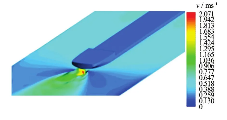
Fig.12(a) (Color online) Velocity distribution on deformed free surface due to prop rotation

Fig.12(b) (Color online) Streamlines colored by velocity magnitude behind the propeller
4.2.1 Influence of ship-bank distance
In this first part, we test the influence of the shipbank distance on the ship behavior in the presence of a propeller. To carry out this study we varied the non-dimensional ship-bank distance between 0.25 and 1.0 and we set the ship speed and rotation speed of the propeller to 0.45 m/s and 123 rpm respectively. The advance ratio is assumed to be 0.75, that corresponds to the high efficiency of the propeller (η0=0.81)and to the following thrust and torque coefficients:KT= 0.15 andKQ=0.028.
The computed results show clearly the additional effect brought about by the propeller on the hydrodynamic forces applied on the hull. A comparison of the results, with and without propeller was performed to show qualitatively the influence of the propeller (see Fig.13).
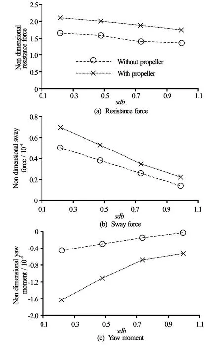
Fig.13 Non-dimensional values versussbddistance
By analyzing the graphs representing the nondimensional forces and moments acting on the hull (ship resistance, sway force and yaw moment), we observe that all curvesshow an identical general tendency, the hydrodynamic forces increase when the ship is sailing close to the bank. However, in the presence of propeller, the following observations were also noted:
(1) An increase of the ship resistance: This phenomenon is due principally to the accelerated flow by the propeller in front of and behind the hull. This acceleration generates an high rate of shear in the hull boundary layer and a low pressure at the rear of the hull. It can be seen from Fig.13 that the curves of the resistance for towed and propelled ship are parallel. This is confirmed by the relationship between the resistance of towed shipRtand self-propelled shipRspgiven by the next formula:Rt=Rsp(1?t),tis a positive number called the thrust deduction. The typical value oftis about 0.2. In Fig.13, the computed thrust deduction number is almost identical over all ship positions and its value is about 0.22.
(2) An important increase in the magnitude of the sway force and the yaw moment. This augmentation can be interpreted by two factors: the first factor is the propeller jet direction (direction of rotation), and the second factor is the absence of the rudder. Without the rudder, the water jet caused by the prop revolution is more dispersed and it is directed at the bank to join the diverging stern waves, which slows the flow on that side. Hence, the pressure increases especially at the stern of the hull (see Fig.14) and the ship heading is directed to bank. However, the lateral distribution of the pressure along the hull dominates and pushes the ship to the channel center. This is represented in curves by the positive sign of the sway force and the negative sign of the yaw moment.
4.2.2 Influence of ship speed
To estimate the influence of ship speed on the hydrodynamic forces around the hull, we fixed the ship-bank distance by choosing a medium non-dimensional distance of 0.6 (corresponding to 0.48 m in scaled model and 5 m in real scale). We then proceeded to vary the speed of the ship and the equivalent rotation speed of the prop using an advance ratio of 0.75, which is considered the best performing ratio.
In the shown tests presented bellow, the speed of the hull is varied between 0.2225 m/s (4 km/h) and 0.55 m/s (10 km/h). The corresponding prop rotation speed is varied between 55.625 rpm and 137.5 rpm.
Figure 15 presents the variation of the computed non-dimensional hydrodynamic forces acting on the propelled hull as function of the ship speed. We note a similar trend for both results, with and without propeller. Although the hull speed variation is the same for each case, we observe that all forces are amplified by adding the propulsive forces, especially when the ship speed is high. This is due, on one side, to the pressure decrease in hull stern generating a supplementary resistance to the ship and on the other side, to the acceleration of the flow around the hull which amplifies the viscous force and modifies the pressure distribution along the hull as well as the lateral force.
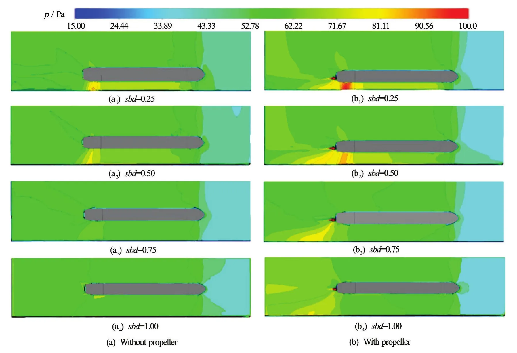
Fig.14 (Color online) Pressure contours around ship for severalsbd
4.2.3 Influence of advance ratio
The last section of this paper treats the impact of the other propeller parameter on the bank effect. This parameter concerns the Advance ratio (J). The advance ratio of apropelleris the distance advanced by the propeller through the fluid in one revolution made dimensionless with the propeller diameter.
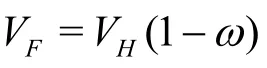
This ratio is given by the following formula:J=VF/nPD. WhereVFis the flow velocity at the inlet of the propeller, andDandnPare the diameter and the rotation frequency of the propeller. The advance ratio takes a high value when the propeller rotation speed is low and the ship is moving at high speed compared with that of the fluid. Otherwise, the advance ratio takes a lower value when the propeller operating at high rotation speed and the ship is moving at lower speed. In this case the thrust and torque coefficients (KTandKQ, see Eqs.(10) and (11)) are very large and the propeller loses its efficiency (η0)because of the high sliding between the prop and the water. In that situation, a high depression is generated at hull stern and can causes a cavitation phenomenon. Hence, the study of the influence of this parameter is very important. Typical values of these coefficients are presented in Fig.16.
Note that the average velocity of the flow at the propeller inlet is usually less than the hull speed, this is due to the viscous flow effect that causes retardation of the flow near the ship boundary layer. The Figs.17(a)-17(b) show the pressure contours at propeller plane and the cross flow vectors colored by velocity magnitude. From these figures we can see clearly the flow acceleration through the propeller plan and the resulting dynamic pressure distribution. Compared with realistic propeller, the use of the simplified body forces method can reproduce an identical radial distribution of thrust, however, the radial distribution of torque remains not identical. This is because the detailed resolution of the blade flow is not taken into account and it is simply represented by an average body forces over rotating cell volume. Hence, the influence of the form and the finite number of blades is not directly considered.
For the following simulations, the propeller characteristics are listed in Table 7. To test the influence of Advance ratio, the non- dimensional ship-bank distance and the ship speed were fixed at 0.46 m/s and 0.4505 m/s respectively. The initial flow velocity around the hull is assumed not variable and the propeller rotation speed varies with the advance ratio. Four values of the advance ratio were tested: 0.25, 0.5, 0.75 and 1, corresponding to rotation speeds 135 rpm, 180 rpm, 270 rpm and 540 rpm.
The influence of theJcoefficient on the hydrodynamic forces acting on the ship is plotted in the Fig.18. The results revealed that the sway force and the yaw moment applied on the hull rise with increaseof the advance ratio. While the ship resistance rise with decrease of the advance ratio.
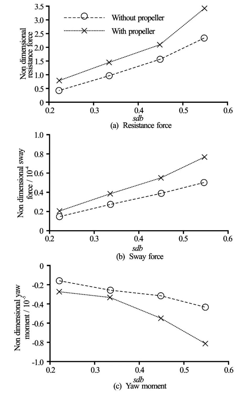
Fig.15 Non-dimensional values versus ship speed
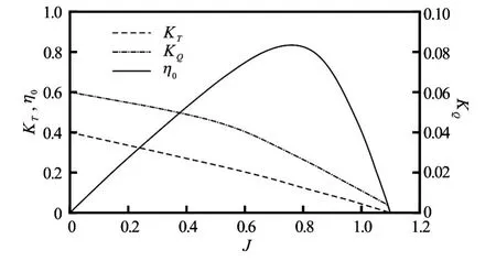
Fig.16 Typical thrust, torque and open water efficiency coefficients versus advance ratioJ[22]
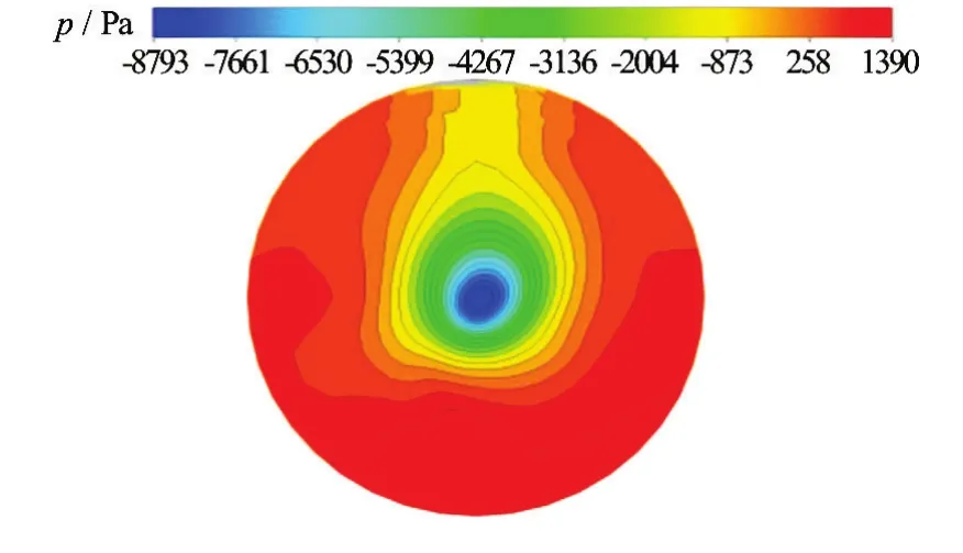
Fig.17(a) (Color online) Pressure contours of propeller plane
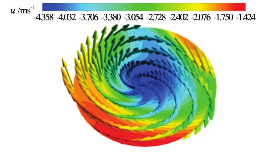
Fig.17(b) (Color online) Cross flow vectors downstream of propeller plan
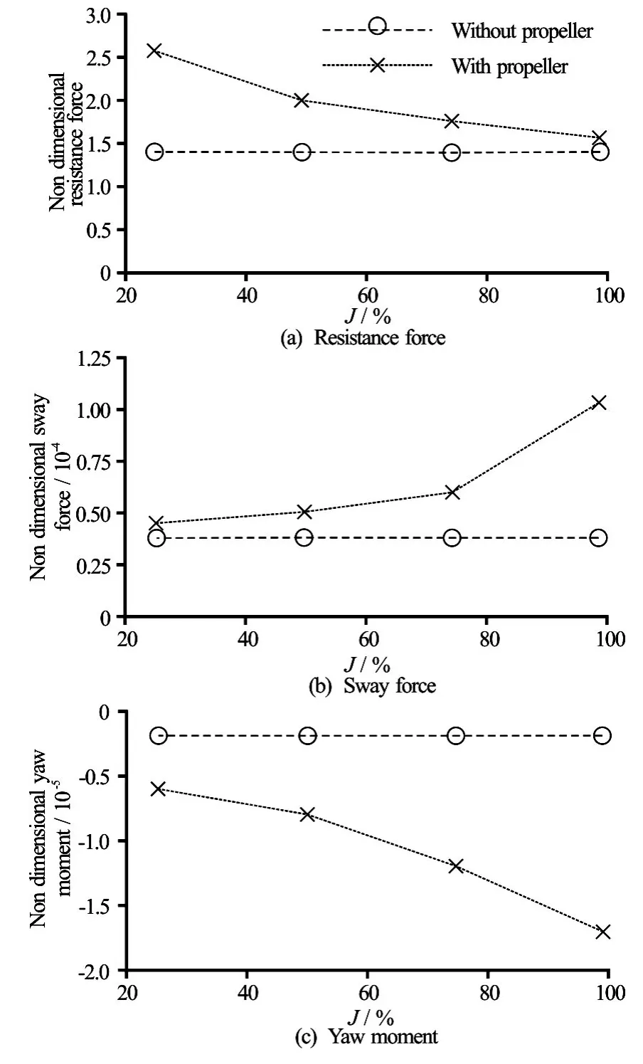
Fig.18 Non-dimensional values versus advance ratio (J)
This is due principally to sliding between the prop and the water. When the Advance ratio is less than 1, the real pitch is lower than the theoretical pitch, hence, the turn more times faster than the inlet water velocity. This makes it possible to decrease the pressure in stern of the hull generating an additional resistance. and the sliding between the water and the propeller blades decrease also the flow acceleration around the hull espe-cially on bank side, which leads to a reduction in the sway force and yaw moment. These results are in agreement with the experimental investigations conducted by Vantorre et al.[5].
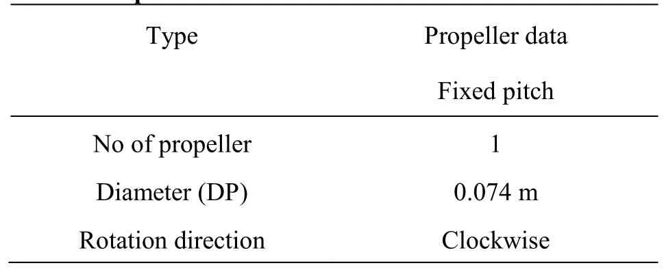
Table 7 Propulsion characteristics
In ideal case (=1)J, the ship resistance considerably decreases and tends to the towed hull resistance. At this value ofJ, a slight difference between both results (with and without propeller) can be seen. This is due to the fact that the incoming velocity seen by the propeller is less than the hull speed because of the wake effect.
5. Conclusions
In this paper a numerical investigation was conducted in order to estimate the impact of the banks on the ship manoeuvrability with and without propeller. A 3-D CFD model based on steady Navier-Stokes equations and the (SST)k-ωturbulence model is used to simulate the flow around the ship. The validation tests of the CFD model revealed that the predicted ship resistance were closer to the measured data.
A preliminary study of the grid convergence was performed for each part of this investigation to choose the optimal mesh. To represent the propeller forces a body-force approach is selected in this work.
The first results concern the study of the influence of ship-bank distance and ship speed on the hydrodynamic forces acting on the ship without propeller. The results show that the hydrodynamic forces due to the bank increase with reduce of the ship-bank distance. And for a given distance between the ship and the bank, the bank effect is proportional to the ship speed and more affected by this parameter.
The second part of this work illustrates the impact of the propeller on the bank effect as function of the ship-bank distance, ship speed and the advance ratio of the propeller. The conclusions yielded show clearly the supplementary effect generated by the addition of the propeller on the hydrodynamic forces acting on the hull. The effect of the two first parameters is represented by an increase in the different hydrodynamic forces in comparison with ship without propeller. The effect of the last parameter is more important, and show that the reduction of the advance ratio, on one side amplifies the sway force and yaw moment acting on the hull, and on the other side decrease the ship resistance.
[1] Norbin N. Bank effects on a ship moving through a short dredged channel [C].10th Symposium on Naval Hydrodynamics. Cambridge, MA, USA, 1974.
[2] Ch'ng P. W., Doctors L. J., Renilson M. R. A method of calculating the ship-bank interaction forces and moments in restricted water [J].International Shipbuilding Progress, 1993, 40(421): 7-23.
[3] Duffy J. T. The effect of the channel geometry on ship operatio in a port [C].30th PIANC-AIPCN Congress. Sydney, Australia, 2002.
[4] Duffy J. T. Prediction of bank induced sway force and yaw moment for ship-handling simulation [C].International Conference on Ship Manoeuvring in Shallow and Confined Water: Bank Effects. Antwerp, Belgium, 2009.
[5] Vantorre M., Delefortrie G., Eloot K. et al. Experimental investigation of Ship-Bank interaction forces [C].Conference MARSIM’03. Kanazawa, Japan, 2003.
[6] Lataire E., Vantorre M., Laforce E. et al. Navigation in confined water: Influence of bank characteristics on shipbank interaction [C].The 2nd International Conference on Marine Research and Transportation. Ischia, Naples, Italy, 2007.
[7] Miao Q. M., Xia J. Z., Chwang A. T. et al. Numerical study of bank effects on a ship travelling in a channel [C].Proceedings of 8th International Conference on Numerical Ship Hydrodynamics. Busan, Korea, 2003.
[8] Lo D. C., Su D. T., Chen J. M. Application of computational fluid dynamics simulations to the analysis of bank effects in restricted waters [J].Journal of Navigation, 2009, 62(3): 477-491.
[9] Wang H. M., Zou Z. J., Xie Y. H. et al. Numerical study of viscous hydrodynamics forces on a ship navigating ner bank in shallow water [C].Proceedings of the Twentieth International Offshore and Polar Engineering Conference. Beijing, China, 2010.
[10] Ma S. J., Zhou M. G. Hydrodynamic interaction among hull, rudder and bank for a ship sailing along a bank in restricted waters [J].Journal of Hydrodynamics, 2013, 25(6): 809-817.
[11] Zou L., Larsson L., Orych M. Verification and validation of CFD predictions for a manoeuvring tanker [J].Journal of Hydrodynamics, 2010, 22(5Suppl.): 438-445.
[12] Zou L., Larsson L. Computational fluid dynamics (CFD) prediction of bank effects including verification and validation [J].Journal of Maritime Science and Technology, 2013, 18(3): 310-323.
[13] Menter F. R. Two-equation eddy-viscosity turbulence models for engineering applications [J].AIAA Journal, 1994, 32(8): 1598-1605.
[14] Sian A.Y., Maimun A., Priyanto A. et al. Assessment ofShip-bank interactions on LNG tanker in shallow water [J].Jurnal Teknologi, 2014, 66(2): 141-144.
[15] Tuck E. O., Taylor P. J. Shallow water problems in ship hydrodynamics [C].Proceedings of 8th Symposium on Naval Hydrodynamics. Pasadena, USA, 1970, 627-659.
[16] Chen X., Sharama S. Nonlinear theory of asymmetric motion of a slender ship in a shallow channel [C].Twentieth Symposium on Naval Hydrodynamics. Santa Barbara, CA, USA, 1994, 386-407.
[17] Ji S., Ouahsine A., Smaoui H. et al. 3D Numerical simulation of convoy-generated waves in a restricted waterway [J].Journal of Hydrodynamics, 2012, 24(3): 420-429.
[18] BAW Code of Practice. Principles for the design of bank and bottom protection for Inland Waterways (GBB) [R]. 2010.
[19] Stern F., Kim H. T., Patel V. C. et al. A viscous flow approach to the computation of the propeller hull interaction [J].Journal of Ship Research, 1988, 32(4): 246-262.
[20] Zhang Z. R. Verification and validation for RANS simulation of KCS container ship without/with propeller [J].Journal of Hydrodynamics, 2010, 22(5Suppl.): 932-939.
[21] Ji S., Ouahsine A., Smaoui H. et al. 3D Numerical modeling of Sediment resuspension induced by the compounding effects of ship-generated waves and the ship propeller [J].Journal of Engineering Mechanics, 2014, 140(6): 682-694.
[22] Triantafyllou M. S., Hover F. R. Maneuvering and control of marine vehicles [R]. Cambridge, Massachusetts, USA: Massachusetts Institute of Technology, 2003.
* Biography:S. Kaidi (1984-), Male, Ph. D., Confirmed Researcher
 水動(dòng)力學(xué)研究與進(jìn)展 B輯2017年1期
- 水動(dòng)力學(xué)研究與進(jìn)展 B輯的其它文章
- Journal of Hydrodynamics, Vol. 28 Annual Classified Catalog (2016)
- Numerical study of the flow and dilution behaviors of round buoyant jet in counterflow*
- Numerical simulation of flow through circular array of cylinders using porous media approach with non-constant local inertial resistance coefficient*
- Insoluble additives for enhancing a blood-like liquid flow in micro-channels*
- Entropy generation analysis for the peristaltic flow of Cu-water nanofluid in a tube with viscous dissipation*
- Study of the natural vibration characteristics of water motion in the moon pool by the semi-analytical method*