
Computing in-situ strength of rock masses based upon RQD and modi fi ed joint factor:Using pressure and damage sensitive constitutive relationship
2015-02-10 02:45:46AshutoshTrivedi
Ashutosh Trivedi
Department of Civil Engineering,Delhi Technological University,Delhi,India
Full length article
Computing in-situ strength of rock masses based upon RQD and modi fi ed joint factor:Using pressure and damage sensitive constitutive relationship
Ashutosh Trivedi*
Department of Civil Engineering,Delhi Technological University,Delhi,India
A R T I C L E I N F O
Article history:
Received 8 February 2015
Received in revised form
15 May 2015
Accepted 28 May 2015
Available online 28 August 2015
Strength ratio Rock mass Plastic parameter Joint parameters Damage Rock quality designation(RQD)
In this study,a new model was presented for computing strength of rock masses based upon in-situ observations of RQD popularly known as rock quality designation.This model links up the rock mass parameters from in-situ investigations with the strength parameters of jointed rocks obtained from laboratory scale experimental observations.Using the constitutive relation,the author derived a pressure and damage sensitive plastic parameter to determine strength of rock masses for varied extents of discontinuity and pressure induced damage.The test results show that plasticity characterized by hardening and softening inclusive of damage invariably depends upon mean pressure and extent of deformations already experienced by rock masses.The present work explores the test data that reveal the dependence of in-situ strength on incremental joint parameters obtained from the joint number, joint orientation,joint roughness,gouge parameters and water pressure.Substituting the relationship between the RQD and modi fi ed joint factor with that between modulus ratio and strength ratio,the model shows successfully that using damage inclusive plastic parameter and RQD provides a relationship for estimating the strength ofrock masses.One ofthe main objectives ofthis work is to illustrate that the presentmodelis sensitive to plasticity and damage together in estimating in-situ strength ofrock masses in foundations,underground excavation and tunnels.
?2015 Institute of Rock and Soil Mechanics,Chinese Academy of Sciences.Production and hosting by Elsevier B.V.All rights reserved.
1.Introduction
Mechanical properties of rock mass interpreted by engineers in fi eld differ signi fi cantly due to the micro-disconformities of strength.The failure theories indicate that the strength is a thermodynamic state depending upon isotropic pressure,which is insigni fi cant at the opening of the discontinuity and reaches a peak at a location of stress concentration.The peak pressure seeks adjustment due to localization of deformation.This process of adjustment,accompanied by plastic deformations,proceeds through a path-speci fi c initial condition to a state often referred to as failure.In the course of compression,rock masses show varied levels of hardening and softening together in relation to the tension,isotropic pressure and peak uniaxial compressive strength of relatively intact rocks.The initial con fi nement for varied joint conditions sets a path-dependent guided deformation up to failure stress.The plastic theories of failure propose the path-dependent guided deformation incorporating stress invariants(I1,J2,J3)(Yu, 2006)where the con fi ning pressure,the magnitude of shear stresses and their directions control the failure behavior.The critical state model(Roscoe et al.,1958)suggests a robust model to explain shear deformation of soft homogeneous granular material which con fi rms that critical state line shifts downward as grading broadens(Li et al.,2015),as that happens in case of increasing the number of joints in rock masses.The behaviors of mass materials, consisting of inherent and induced discontinuities,anisotropy,and non-homogeneities,namely,rock masses,require considerations of cumulative plastic strains in a relatively intact and fully adjusted state,which can be explained realistically by the disturbed state concept(DSC)(Desai,2015a,b).
During deformation,all the mass materials show conservative and dissipative work components.With the progress of plastic deformation,there is a zone ofplastic fl ow.As a result,a component of work dissipates as a scatter of thermal output,often ignored in rock engineering practices.The limited plastic fl ow,carried forward at varied strength ratios,is the cumulative irrecoverable strain, which fi nally develops into continuous joint.The strength ratio (σmr)is a ratio of the strength(σm)of rock mass containing anetwork of joints to unixial compressive strength of intact rocks (σr)where the network of joints is microscopic.With the progress of loading,a fl ow rule depending upon a plastic potential function captures the plastic fl ow.The deformation of fractured rock mass undergoes hardening and/or softening,which makes it hard or soft on yield relative to its reference state.In other words,the hardening mode sets a condition for contraction,while the softening assumptions permit gradual dissociation of grains at micromechanicallevel(Fig.1).Such microscopic dissociations,frequently bringing con fl icting deformation in rock masses at macromechanical level,are often mapped by jointing patterns visible on scan line survey as captured by the rock quality designation (RQD)(Table 1).The RQD is one of the most popular rock investigation techniques.It uses directly the in-situ core recovery data of rock mass and is de fi ned as percent recovery ofintact pieces of rock core larger than 10 cm to the total length of drilled core(usually 100 cm)as proposed by Deere et al.(1967).Therefore,the present work proposes a relationship between strength ratio and RQD incorporating nonlinearity owing to rock mass mapping and intrinsic joint characteristics.The mean con fi ning pressure(pi)induces a progressive hardening or softening through strain energy storage,respectively,up to a value related to uniaxial compressive strength of intact rock(σr).This strain energy dissipates at a rate depending upon a pressure sensitive dissipation process.
1.1.Evolution of pressure and damage sensitive plastic parameters
Drucker and Prager(1952)and Drucker(1959)described in their seminalwork that the mass materials may experience isotropic and kinematic hardening(Shield and Ziegler,1958)and softening.The temporal softening process invokes a plastic fl ow as postulated by several investigators(Roscoe et al.,1958;Hirai and Satake,1982; Spitzig and Richmond,1984).Based upon these concepts,the author considered a transition of yield surface due to a progressive plastic fl ow for the rock mass,which transforms in the stress space. The yield surface may expand,contract,change its shape or translate upon loading and yield characterized by a pressure to set a plastic fl ow.Then a fl ow rule governs the evolution,both in the magnitude and in the direction of the plastic strain rate with the stress and stress increment.Additionally,a hardening or softening rule accompanying damage provides scope for modi fi ed yield conditions during plastic fl ow.Based upon this concept,at an ambient temperature and initial isotropic pressure(pi/σr),the joint hardening or softening occurs at a nonlinear rate.Therefore,this study recognized a pressure dependent and a pressure-temperature coupled nonlinear plastic parameter(<Chs>)at granular level for unit changes in joint damage parameter(<hhs>).<Chs>is piece-wise continuous in hardening or softening range,within the limits of?and?,such that they correspond to?><Chs>>?.If?→0, the work is conserved,and the deformation is independent of joint contraction or dilation.The joint damage parameter is a ratio of modi fi ed joint factor(Jfg)in hardening and softening ranges.For an initial value of the plastic parameter,?><Chs>>?,the rock masses undergo deformations with the effects of con fi nement,shape and size.The modi fi ed joint factor is physically estimated fromjoint and in-situ rock mass characterization,namely,RQD,with consideration of cumulative plastic strains.Although there are several variants ofdilatancy dependent plastic parameter in the contemporary engineering literature(Taylor,1948;Rowe,1962,1969;de Jong, 1976;Bolton,1986;Yuan and Harrison,2004)which consider cumulative plastic strains,one of the most popular de fi nitions consists of the percent volume change following plastic deformation divided by the magnitude of the shear strain.If the ratio of shear stress to isotropic pressure is such that volume increases,then the specimens are strong at yield and hence dilate(Scho fi eld and Wroth,1968).
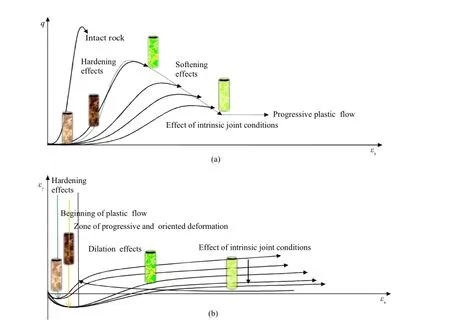
Fig.1.Shear-volume change characteristics of rock masses under mechanical loading.
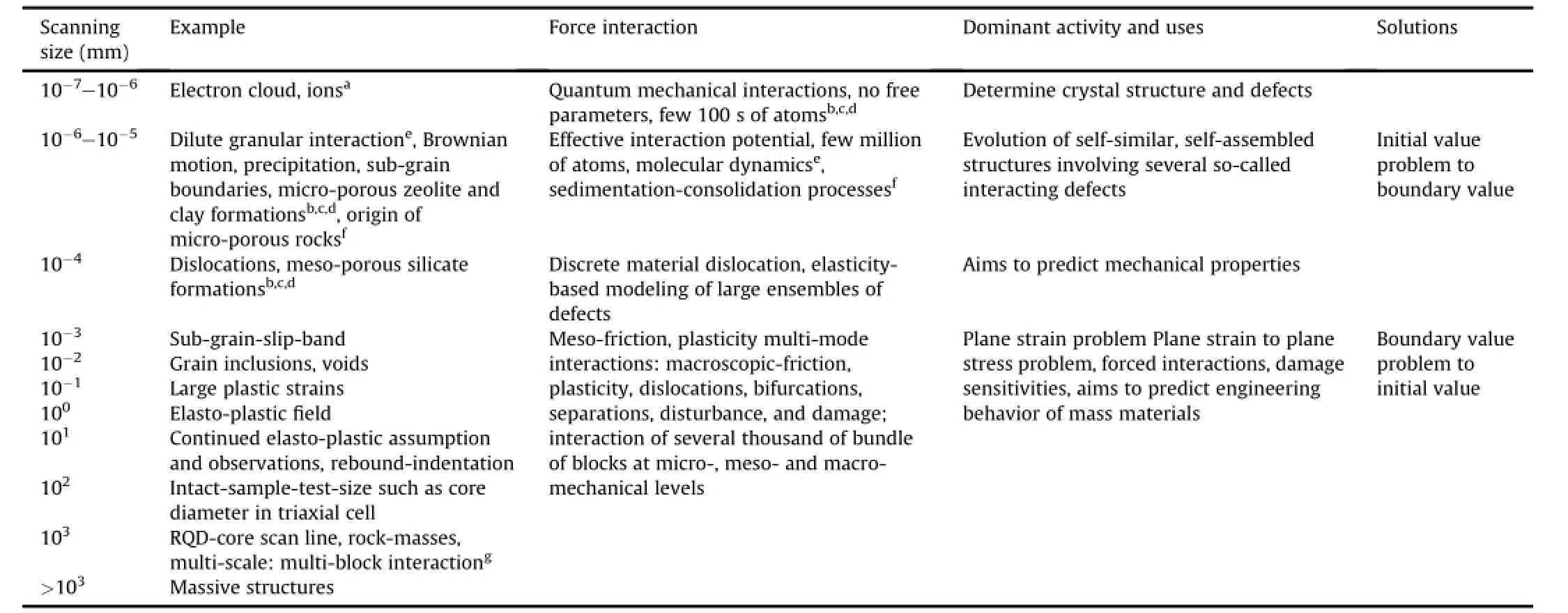
Table 1 Scan line survey for multi-grain,multi-block,block-grain interaction in mass materials and engineering solutions.
The force interaction at varied scales and plastic dilatancy experienced by various mass materials,namely,metals,soils,and rocks,vary in a widely signi fi cant range as reported in Tables 1 and 2,respectively.The author envisaged a relationship for volume change characteristics with the damage sensitive plastic parameters which varies between?and?covered by the range ofhardening and softening parameters affected by the applied pressure.It relates the strength of rock mass to the joint parameters with plastic parameters in selected range of observed values(Table 3).
Several early investigators such as Bieniawski(1978)and Sera fi m and Pereira(1983)af fi rmed that varied in-situ states, conditions and boundary settings may produce different deformations.The loading and boundary settings indirectly refer to the path sensitive deformations as duly considered in this work. This work conceives a consistent model for rock masses which connects the strength with a pressure sensitive plastic parameter including progressive failure(Trivedi and Sud,2005)using constitutive relationship from the laboratory test data to in-situ testing, namely,RQD.
Historically,varied rock mass classi fi cation systems,namely, rock mass rating(RMR)by Bieniawski(1978)and Nicholson and Bieniawski(1990),and geological strength index(GSI)by Hoek and Brown(1980),Hoek(1983),Hoek and Diederichs(2006),and Hoek and Martin(2014)using their proli fi c experiences,considered a set of fi eld observations to propose compressive strength of rock mass.Hoek and Brown(1980)derived their strength criterion on the basis ofa vast amountofdata and knowledge gathered fromthe deformation of concrete which in fact has a strength comparable to intact rocks,both consisting of micro-disconformities.Kalamaras and Bieniawski(1995)used RMR,which included the joint spacing,and RQD to predict strength of rock mass.Martin et al. (1999)considered tunnel instability and brittle failure as functions of RMR and the ratio of the maximum far-fi eld stress to the uncon fi ned compressive strength.Villeneuve et al.(2012)considered the effect of grain scale heterogeneity on rock strength and the chipping process which is conceived as fragmentation of joints in several studies.As per Terzaghi(1946),the joints are among the most important causes of overbreak and of troubles induced by water,and they always deserve careful consideration.Additionally, RMR and GSIpresent a measure of qualitative assessmentofjointed rock masses.The Q-system(Barton,1986,2013)considered six parameters including RQD,joint number,roughness,effect ofgouge,conditions of joints,groundwater condition and stress reduction factor.McLamore and Gray(1967)pointed out the signi fi cant effect of the joint inclination on the strength of jointed rocks at low con fi nement.Ramamurthy and Arora(1994)and Trivedi(2010)considered joint parameters consisting of joint number,orientation,roughness and block to propose the strength of jointed rock mass based on statistical and numerical analysis, respectively.Priest and Hudson(1976)and Sen(1984)proposed a relationship between discontinuity spacing and RQD to capture insitu state of rock quality designated on a broad scale.
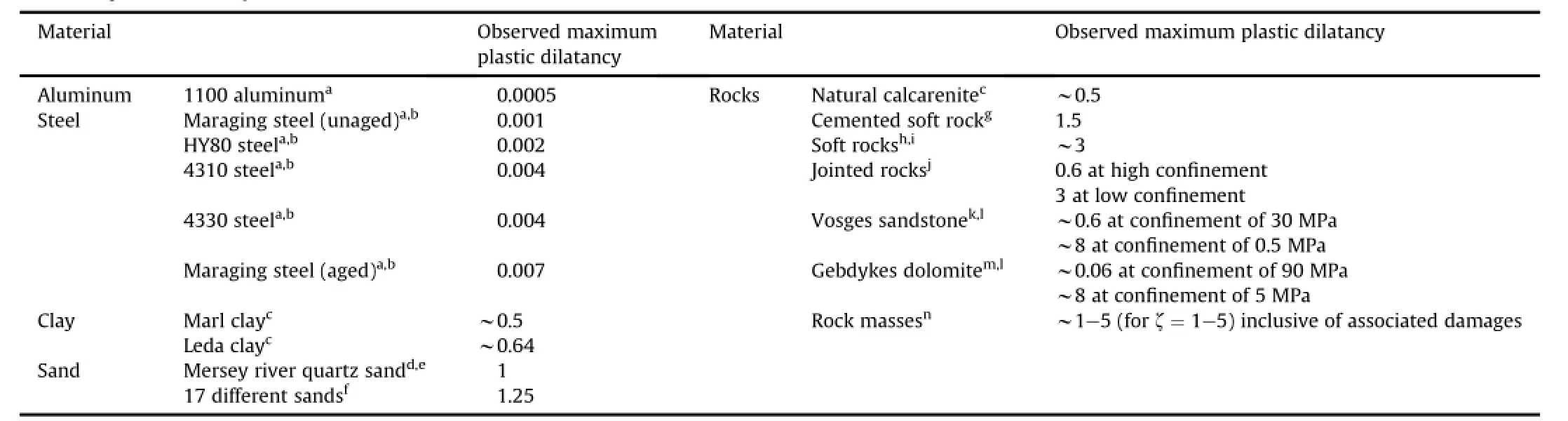
Table 2 Observed plastic dilatancy for various mass materials.
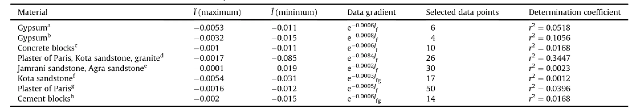
Table 3 Estimates of the maximum(?)and minimum(?)values ofαp.
The deformation obtained from joint number,vertical and horizontal stiffnesses(Zhang and Einstein,2004;Zhang,2010; Trivedi,2013a,b)provided a correlation with RQD obtained from different sources.The relationship between joint stiffness characteristics and rock mass deformation(Zhang,2009)leaves a scope to consider a pressure and damage sensitive plastic parameter dependent on joint characteristics in order to predict strength of rock mass from RQD.
The equivalent continuum model(ECM)considers the rock mass as a continuum that re fl ects the deformations of both the intact rocks and discontinuities(Zhang,2010).The ECM uses some of the strength properties of intact rocks and discontinuities from the laboratory as wellin-situ tests as compared in Tables 4 and 5,where UCS is the uncon fi ned compressive strength.
1.2.Scope of study
The early studies left a scope for estimation of pressure and damage sensitive parameters of rock masses as one of the unsolved issues.The strength of jointed rock mass was yet to relate a readily obtained plasticity unifying hardening,softening and damagesensitivities with experimentally estimated quantities obtained through measurements such as joint parameters and RQD.
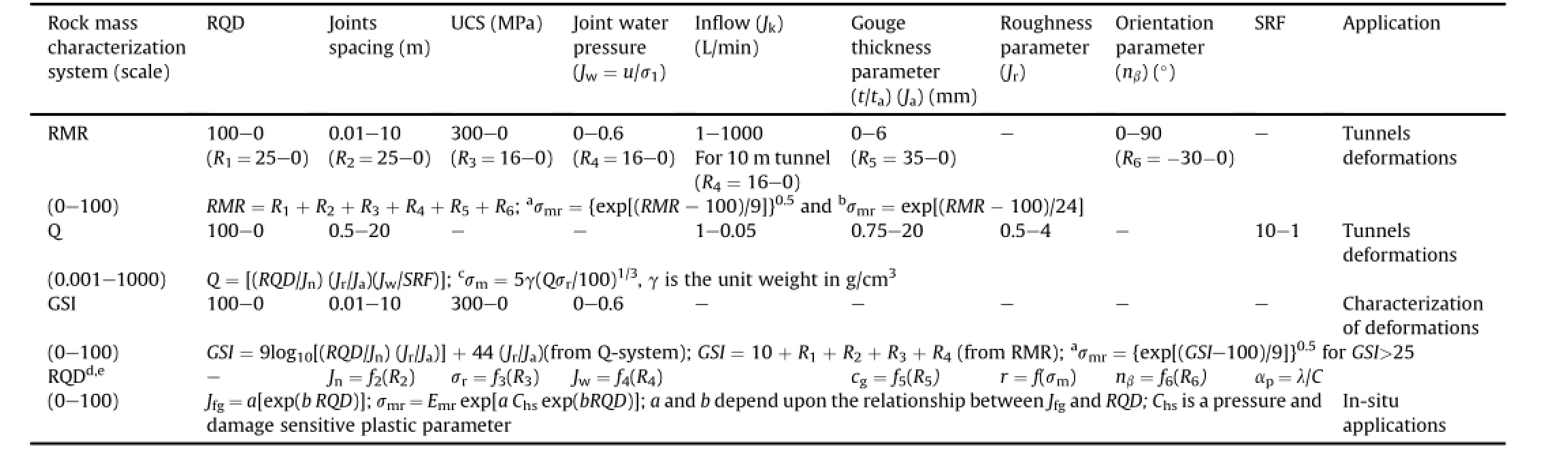
Table 4 Strength ratio from rock mass characterizations systems(RMR,GSI,RQD and Q-system).
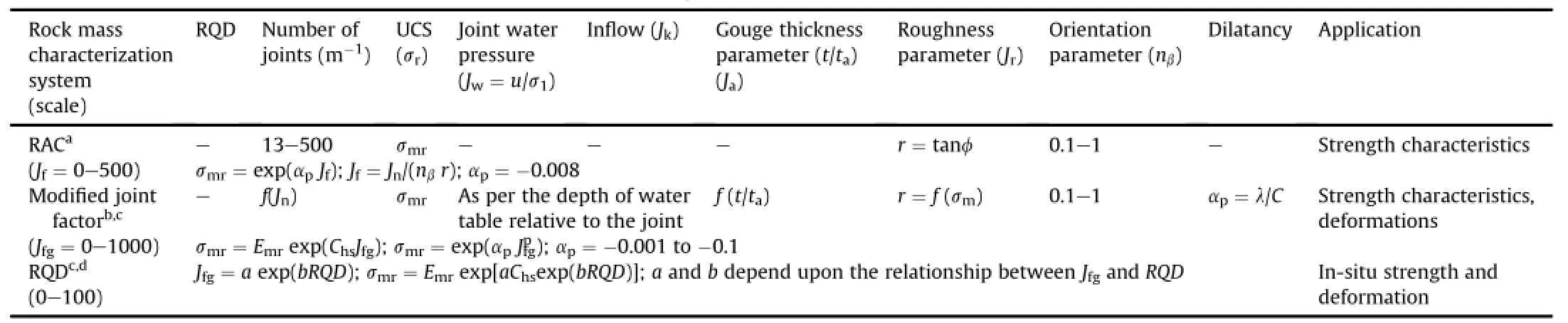
Table 5 Strength ratio from laboratory and in-situ characterization systems(RAC,Jfg,and RQD).
Based upon the observations,the key features of the present study are presented as follows:
(1)The rock masses have characteristics of inherent and induced discontinuities,micro-structural dissociations,fractures,and massive non-homogeneities,namely,gouge.The inherent discontinuities normally present in the rock mass.The induced discontinuities are produced due to the presence of pressure.
(2)The rock masses consist of elastic and damage coupled plastic deformations.
(3)The stress invariants conveniently express the behavior of rock masses.
(4)The empirical data including JC-criterion(Johnston and Chiu, 1984;Johnston,1985)provide a basis for obtaining yield functions.
(5)A pressure sensitive plastic parameter relates the initialto fi nal conditions of joint and plastic yield.
(6)The experimentaldatabase provides a relationship between the rock mass strength and Jfgusing a softening parameter.Similarly,there exists a relationship characterized by a hardening parameter between modulus ratio and Jfgin the hardening range.
(7)The in-situ exploration of rock mass provides a relationship between Jfgand RQD.
(8)Using the concept of joint damage,hardening and softening,a pressure sensitive plastic parameter is evolved.
(9)A pressure and damage sensitive plastic parameter connects strength of rock mass with RQD,which allows considering the effects of cumulative plastic strains and damage together.
The present study proposes that rock mass strength parameters should be re-examined to have potential for capturing extent of damage and plasticity,unifying effects of anisotropy,joint orientation,discontinuity frequency,presence of gouge,water pressure and especially plasticity due to the con fi nement and direction of shear stresses frominitialto fi nalconditions of failure in relation to the in-situ tests.A modi fi ed joint factor(Jfg),observed during rock explorations,considers intrinsic rock mass characteristics,i.e. discontinuity frequency such as joint number found from scan line, roughness from friction parameter,joint inclination using orientation parameter(Table 6),joint and gouge conditions,density of gouge,groundwater and stress conditions,to be incorporated in strength(Tables 4-6).
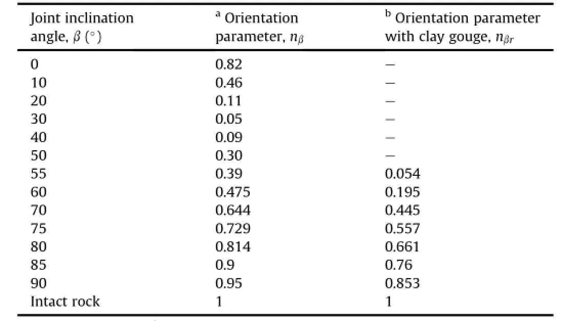
Table 6 Orientation parameters for different joint inclinations of blank and gouged joints.
In this paper,the plastic parameter was obtained numerically for input of isotropic pressure ratio(pi/σr),which was set into rock mass as per JC-criterion.The rock mass tends to reach failure upon loading.It was conceived in strength ratio(σmr).The strength ratio is obtained from laboratory tests on intact rock and jointed rock samples.It is in fl uenced by the direction of joints,which in turn in fl uences direction of shear stresses(J3).The strength ratio(σmr) has been captured as a function of joint parameters,namely, modi fi ed joint factor(Jfg),and plastic parameter(Chs).The strength loss as an effect of jointing pattern used in the present work has similar effects on DSC proposed by Desai(2015a,b),which recognizes a relatively intact strength and fully adjusted state where the effect of damage inclusive cumulative plastic strain may decrease strength values to be lower than the values predicted by the critical state model.
2.Preliminary de fi nitions
2.1.Strength ratio
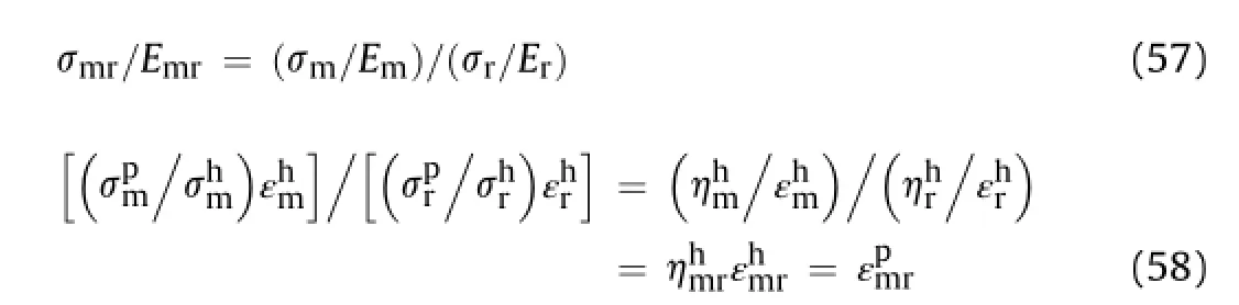
The strength of rock masses(σm)is evaluated in terms of strength ratio(σmr)which is a ratio of strength of rock mass(σm)to that ofintact rock sample(σr)ofthe same size and shape.One ofthe main aims of fi nding strength ratio in terms of signi fi cant joint parameters,namely,modi fi ed joint factor,is to get readily the strength of rock mass by conducting uniaxial compression test on the intact rock.Ifσ1m,σ2mandσ3mare the principal stresses in the rock mass andσris the compressive strength of intact rock sample in uniaxial test,then in the triaxial case,the ratio at failure is expressed as
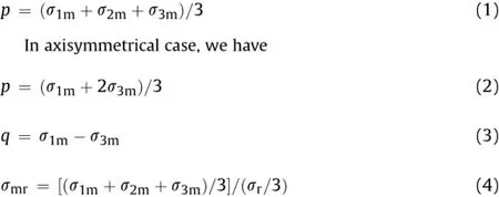
According to Eqs.(1)and(4),we have
The mean con fi ning pressure ratio and shear stress ratio in axisymmetrical case are respectively de fi ned as
Under triaxial condition,the modulus ratio is represented as

where Erand Emare the deformation moduli de fi ned as stress and strain ratio of intact rock and rock mass,respectively,at varied strain levels in a selected range of pressure.
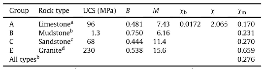
Table 7 Trialparameters for yield surfaces(Johnston,1985).
2.2.Intrinsic joint characteristics:joint number,joint factor and modified joint factor
The strength of rock masses depends on the presence of a number of joints.The joint number(Jn)is de fi ned as joints number per unit length of a scan line.The assigned joint number is an equivalent directionalparameter based upon the occurrence of the joints.The orientation of the joint shows its tendency of slipping and shearing in a selected direction.It may obstruct or facilitate the joints to contract or dilate at different rates once stress is applied. The joint set per unit volume considers equivalent joint frequency, its orientation,and quantity of frictional granular fi ll.According to Arora(1987)and Ramamurthy and Arora(1994),the joint set is multiplicatively equivalent to joint factor(Jf).According to Trivedi (2010),a modi fi ed joint factor(Jfg)was proposed to capture the multiplicative equivalence ofallthe rock and gouge parameters and their transition as the loading proceeds.Arora(1987)and Trivedi (1990)obtained the orientation parameter for the blank and gouged joints as shown in Table 6.
The modi fi ed joint factor relates the joint number(Jn)and the modi fi ed joint factor(Jf)to joint and gouge parameters,presented in dimensionless form as
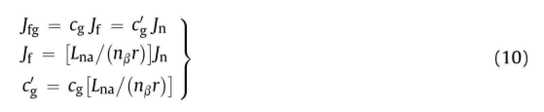
where nβis the orientation parameter related to the angle between joints orientation and the direction of loading(β)or to the friction parameter(r).The reference value of friction parameter r=1,and the reference value of length parameter La=1 m.
Based upon the experimental results of several investigators (Yaji,1984;Arora,1987;Trivedi,1990;Arora and Trivedi,1992;Trivedi and Arora,2007;Trivedi,2010,2013a,b),the author considered varied engineering parameters of rock masses from laboratory tests in relation to fi eld investigations to de fi ne cgas
Table 8 Plastic parameterαpfor rock mass from numerical trials.
where J dj is the modi fi ed coef fi cient for joint depth(joint stress parameter);Jtis the modi fi ed coef fi cient for thickness of gouge (gouge thickness parameter);gdis the modi fi ed coef fi cient for the compactness of joint walls and relative density of granular fi ll, namely,gouge,which equals 1 for fully compacted joints;Jwis the modi fi ed coef fi cient for groundwater conditions.
Accordingly,the gouge is a hydro-thermal deposit in rock masses which may allow the fl ow of water through the joints measurable in terms of permeability(Singh et al.,2014).The consolidated and unconsolidated gouge in rock masses(Trivedi et al.,2014,2015)may increase or decrease the strength.The grains in the discontinuity tend to consolidate or dilate during loading.refer to the instantaneous values of modi fi ed joint factor(Jfg)in the hardening and softening range,respectively, separated by a saddle pressure at a maximum value of damage sensitive plastic parameter characterized by?.The effect of pressure sensitive plasticity on rock mass parameters,stress condition (plane stress and plane strain)and Emris listed in Tables 7-9, respectively.The progressive compression and dilation of in fi ll infl uence the strength and deformation characteristics of rock masses.In the water pressure induced fi eld condition,Jwmay be considered as a linear function of excess pore pressure parameter (in a range of 1-0.05)(similar to the Q-system by Barton(2013)). Similarly,Jwis indirectly estimated from the groundwater parameter R4of RMR system(as R4in Tables 4 and 5).
Since in the hardening range,while in the softening,strength ratio at failure is

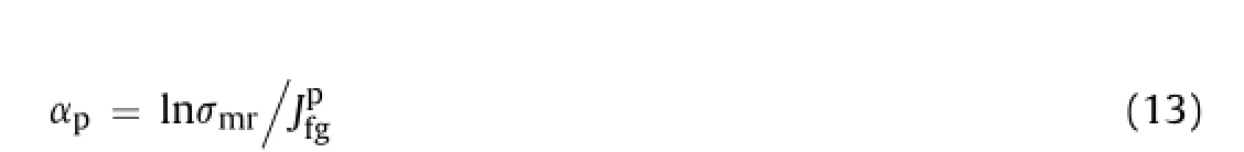
whereαpis a fi tting parameter.The values ofαpappear in a wide range,as shown in Table 3.
Alternatively,Eq.(12)can be rewritten as
Similarly,we have
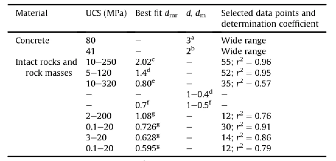
Table 9 Relationship between UCS and modulus ratio.
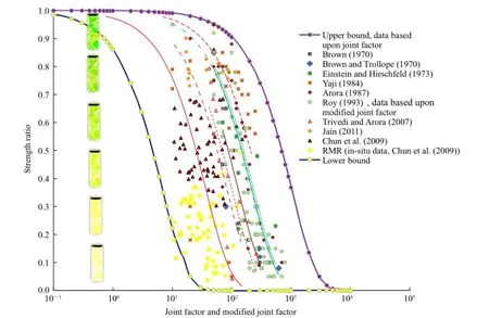
Fig.2.Strength ratio vs.joint factor and modi fi ed joint factor.
where Chis a pressure and joint dependent hardening parameter.
Fig.2 shows compiled experimental data of strength ratio and modi fi ed joint factor obtained by various investigators including the data obtained fromin-situ observations of GSIand RMRsystem. The upper bound values correspond to the laboratory controlled studies while the lower bound values are obtained from in-situ observations.
Table 3 shows low values of determination coef fi cient and maximum and minimum values ofαpbased upon joint factor and modi fi ed joint factor in the past studies.It is important to note that not all these studies necessarily capture the plastic and damage induced volume change during deformation.
2.3.Joint strains,volume changes and yield function
According to elastoplastic theory,the total strain increment consists of elastic and plastic strain increments as an effect of pressure,temperature and resultant shear.The global change of strain is adjusted primarily among joints and later it transforms joints by means of irrecoverable strains(3p).The irrecoverable strains consist of volumetricshear and damage componentswhich are distinctively related to volumetric and shear stresses,respectively.The volumetric stresses produce joint closure and separation leading to a volume change.As an effect, damage-inclusive plastic shear strain and joint shear stresses are induced.Therefore,potential of initial isotropic stresses and joint strain relative to plastic volumetric strain and joint shear stresses respectively is always present in rock masses.The notions of stress and strain are interlinked to the joints.At the fundamental level they are related by mechanicalpower,and the rate of work per unit current volume of the rock mass material,but the effect is measured in terms of joints.Therefore,due to the applied stresses, the effect of joint is measured instead of that of strain.
Therefore,the total strain is presented as

The plastic strain can be formulated as

The plastic shear and damage strains are considered as
For rock masses without gouge,joints are orthogonal to loads and reference friction parameter,thus we
For conditions without damage and insigni fi cant presence of
The relationship of cumulative plastic strain,amid the anisotropic potentialofplastic strain in pressure-joint regime(ij)in rock masses,may be represented in terms of commonly used notations in continuum mechanics as
Similarly,the stress tensor(σmn)is related to a strain tensor(εkl) using a compliance matrix(Cklmn)as
Fig.3.Evolution of horizontal and vertical joints.βis the inclination of joints to the direction ofloading.(a)Jn=30,β=90°;(b)Jn=60,β=90°;(c)Jn=120,β=90°;(d) Jn=30,β=0°;(e)Jn=60,β=0°;(f)Jn=120,β=0°.
where the subscripts k,l,m,n=1,2,3 are used for tensorial representation.
The scalar modulus ofstress in pressure-joint regime(ij)may be represented asσij=(σmn)1,2,3which is resolved into(p,q,Chs)space, such that,if m=n,σnn=σij=f(p);and if m≠n,thenσmn=σij=f(q). Moreover,if|j|→+∞,|σij|→0.
However,the use of tensorial indices has been omitted in the following arguments for simplicity.The application of fulltensorial form can be quite complex to handle numerically in presence of non-coaxialplasticity and damage.Fortunately,most of the implicit features of fractured material(namely,rock masses)behavior(p,q, Chs)can be described using scalar models in deformation fi elds (Herrmann et al.,1989;Herrmann and Roux,1990;Zapperi et al., 1997).
In the pressure-joint regime,the size ofyield surface is assumed to be affected by softening of cemented bonds as per the observations in experiments(Horpibulsuk et al.,2004).The effect of hardening and softening due to pressure-temperature coupling and joints may be considered together for the plastic yield.Thus, the yield function for rock mass is de fi ned as

where Chsis the plastic parameter depending on hardening and softening evaluated in a potential pressure-joint regime(ij).

Fig.4.Evolution of inclined joints.(a)Jn=30,β=45°;(b)Jn=60,β=45°;(c)Jn=120, β=45°;(d)Jn=150,β=45°;(e)Jn=240,β=45°;(f)Jn=480,β=45°.
Theoretically,the incidental value of modi fi ed joint factor(Jfg) has an effect of time history in terms of already experienced dilatancy and damages of rock joints:
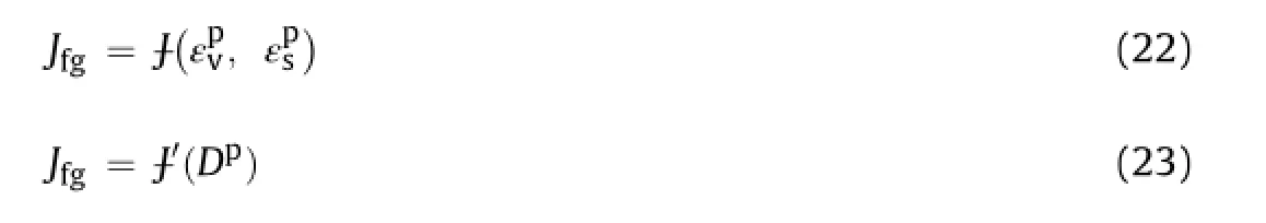
where Dpis the damage-inclusive plastic dilatancy,which considers change in volume and is associated with shear distortion and damage.It is a function of plastic volumetric strain,plastic shear and damage in intact rock,rock mass and gouge material.
2.4.Direct measurement of rock mass characteristics and damage through RQD
In-situ rock masses consist of discontinuity,inclusions and weaknesses.The weak formations are relatively more vulnerable to damage upon loading and unloading.Therefore,the weakness reappears prominently within a continuous deposit subjected to a combination of stresses due to the drilling associated process.The drilling process recovers a core of rock mass while joints appear as discontinuities at unequal intervals.Normally the average joints number is counted in the unit length of the scan line.Figs.3-5 shows idealized rock joint parameters in the rock core as functions of modi fi ed joint factor and RQD.Fig.6 shows the gradual closure of joint pattern due to pressure-induced hardening while Fig.7 shows gradual impairment of rock mass as an effect of pressure-induced softening.
Field investigations to obtain RQD consist of the orientation of the joints relative to the direction of the scan line to obtain orientation parameter.The core recovery log should be speci fi ed additionally to get record of orientation on the data sheet of bore log. The geotechnicalapplications consider RQD as a percentage ofscan line consisting of intact samples greater than 100 mm,which is presented as
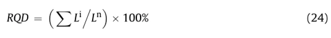
where Liis the length of intact piece of core in a scan line having size equal to or greater than 100 mm,and Lnis the total length of drill length for core recovery.
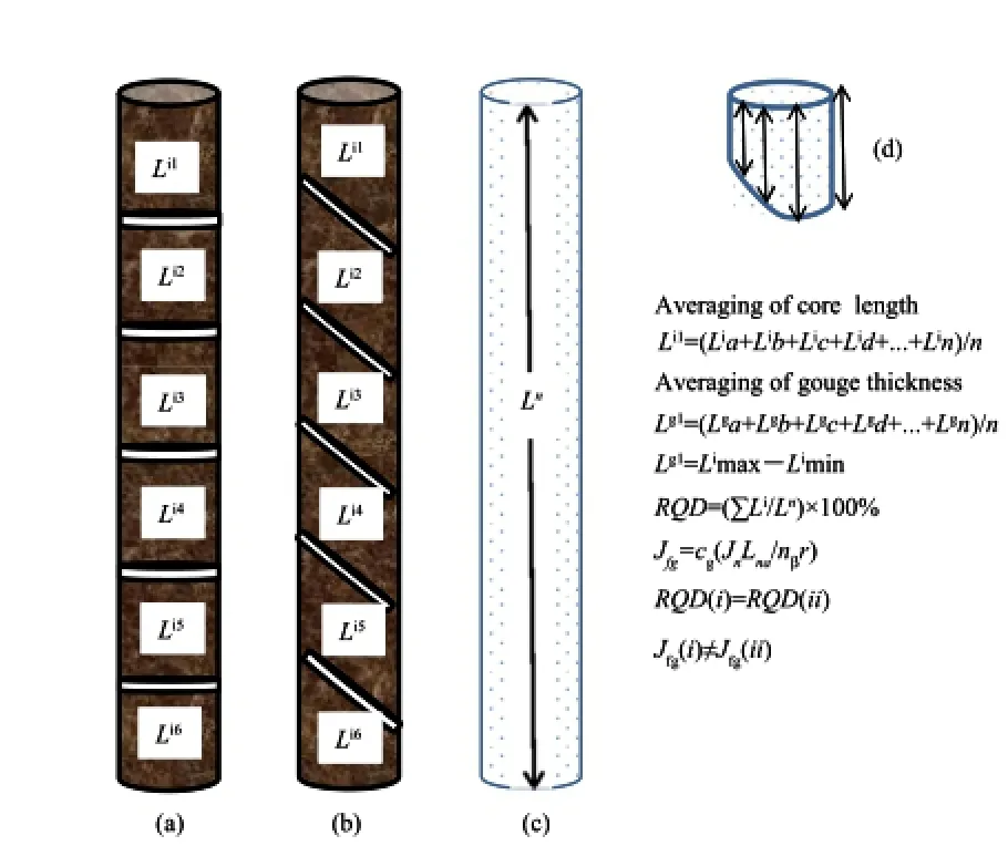
Fig.5.Consideration ofhorizontaland inclined joints in RQD and modi fi ed jointfactor. Li1is the length of the fi rst core segment,and Lg1is the thickness of the fi rst gouge segment.(a)Jn=5,β=90°;(b)Jn=5,β=45°;(c)Intact core with length of Ln=1 m; (d)Core segment,β=45°.
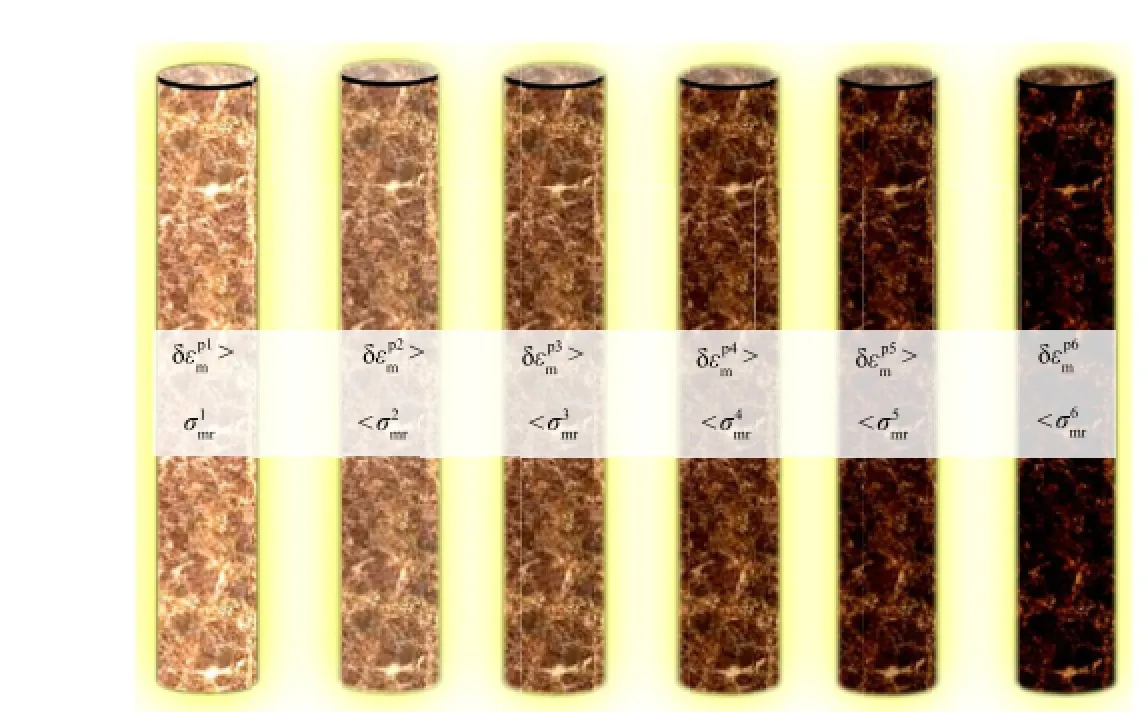
Fig.6.The evolution of hardening and damage in six stages as an effect of accumulated plastic strains in hardening range to increase strength at all possible values of modi fi ed joint factor at selected RQDs.
The RQD appears to be a qualitative parameter in rock mechanics that has a lot of challenging questions.There is a quantitative evaluation system available to supplement RQD(such as the parameters considered in calculation of modi fi ed joint factor) based upon fi eld geotechnical investigation and a pressure and damage sensitive plastic parameter obtained from constitutive relationships.The RQD(as considered by Deere and Deere(1988))can yet be supported and improved by a set of re fl ective parameters(as parameterized in modi fi ed joint factor Jfg).In a similar attempt, severalresearchers introduced other parameters to describe quality of the rock mass,such as Q-system,GSI,and RMR.
Priest and Hudson(1976)proposed that the estimate of RQD should be related to joint spacing measurement of the core as

They also suggested a modi fi cation for the joint number ranging from 6 to 16 per meter represented in parametric form as

where RQDfnis a value of RQD that is not necessarily observed in the RQD scale but appears in empirical relationship due to linearization.Here in Eq.(26),RQDfn=110.4,nl=3.68.
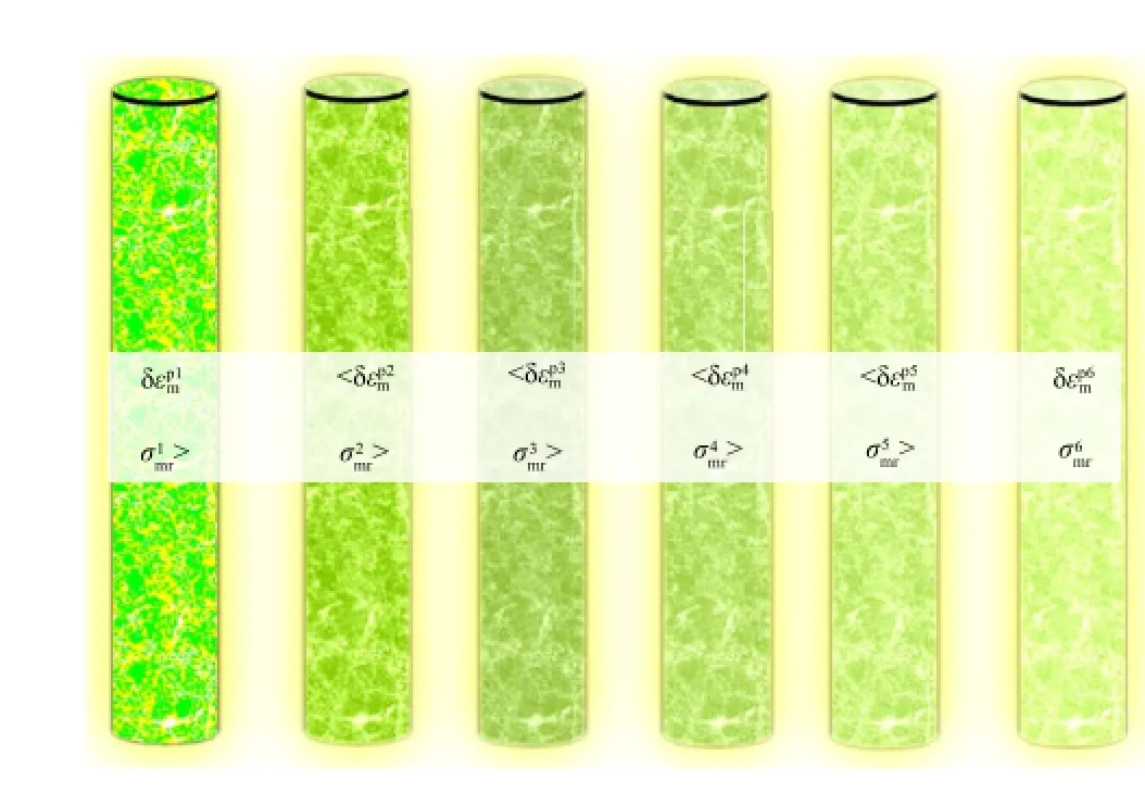
Fig.7.The evolution ofsoftening and damage in six stages as an effect ofaccumulated plastic strains in softening range to decrease strength at allpossible values of modi fi ed joint factor at selected RQDs.
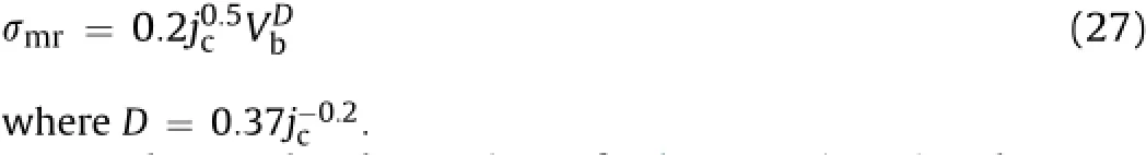
Palmstrom(1996)considered block volume Vb(related to joint frequency),and joint condition(jc)including roughness of joints to propose the rock mass strength:
Based upon the observations of Palmstrom(1996)and Grenon and Hadjigeorgiou(2003)that neglected volumetric joint count and thus would estimate erroneously the discontinuity pattern in rock masses,Palmstrom(2005)proposed the joint number per unit volume(nvJv=nlJn)instead of Jn,which may be represented as

There are inherent similarities between Eqs.(26)and(28).As per Palmstrom(2005),RQDfvis equal to 115,the value of nvmay be 3.3 and nl/nv=1-6,therefore the range of nlmay be as high as 1-20. Eq.(28)is applicable if the volumetric joint count(Jv)is 4.5-35. The relationship between RQD and volumetric joint characteristics (Eqs.(26)-(28))provides a scope for further analysis of intrinsic joint characteristics.The minimumvalue ofjoint volume in Eq.(28) for intact rocks nearly equals 4.5%,which is not necessarily consistent with the in-situ observations as shown in Fig.8 where the effects of accumulated plastic strains and scale effects are considered(up to b=-0.05).In fact,the observation of RQD for rock masses(Eqs.(25)-(28))is essentially exclusionary in nature, which offsets the in fl uence of drill mass sizes less than 10 cm.In order to fracture initiation at micro-to meso-scale and accumulated plastic strain,the author proposed to relate RQD with intrinsic joint characteristics(b=-1 to 0.01).
2.5.Relationship between RQD and intrinsic joint characteristics
Sen and Eissa(1991)examined the use of lognormal and negative exponentialrelationships between RQD and joint volume. They showed that decreasing RQD value with increasing difference in length of block side or joint spacing,the changes in block size tend to adjust the stress intensity at discontinuities.These observations call for modi fi cation of the relationship between RQD and joint and gouge parameters,namely,extent of joints,volume of gouge,friction,material of gouge,and water pressure.The scan line as well as the volumetric joint count has an exponential relation with RQD as the block size changes with increasing in fi ll magnitude.At RQD=0,the recovered rock core sizes are less than 10 cm (relatively fragmented state),the rock mass strength characterization should ideally be captured using parameters considered in the calculation of modi fi ed joint factor,Jfg.Other than RQD and modifi ed joint factor,there are more parameters,namely,total core recovery(TCR),solid core recovery(SCR)and core recovered from the following run(CRF),which can also be used to map the rock mass classi fi cation at RQD=0.Based on limited data available,it may be stated that TCR,SCR and CRF similar to RQD(Eid,2007;Valentine and Norbury,2011,2012;Nicholls,2012)do have inverse relationships with Jfg.
On the basis of previous studies(Sen,1984;Sen and Eissa,1991; Grenon and Hadjigeorgiou,2003;Palmstrom,2005;Trivedi, 2013a,b),an exponential relationship between modi fi ed joint factor and RQD is proposed as
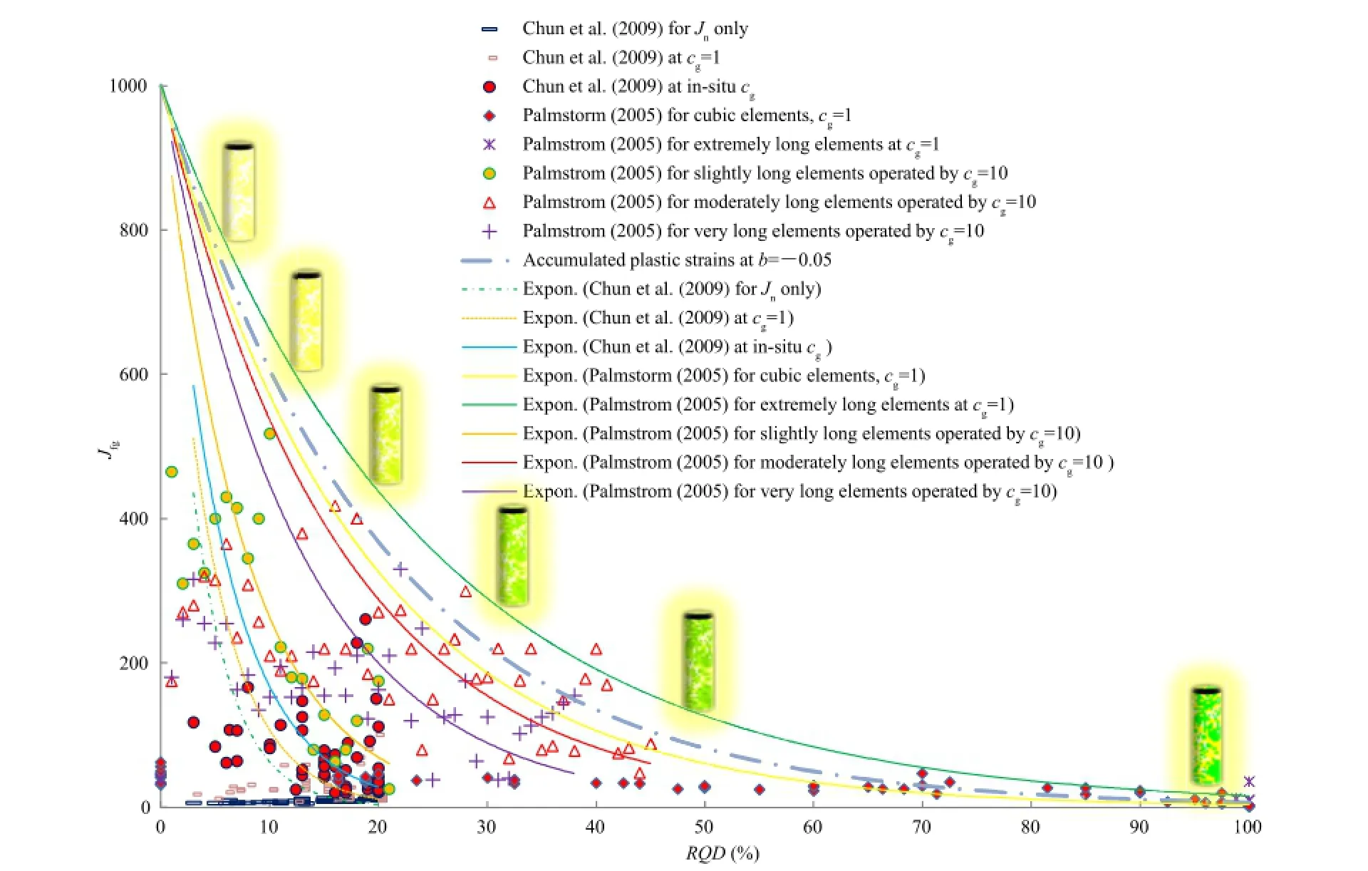
Fig.8.Variation ofmodi fi ed joint factor with RQD at cg=1 for lower bound and cg=10 for upper bound of the maximum accumulated plastic strain.
where a and b are the fi tting parameters determined according to the minimum size of fragmented rock and characteristics of joints in relation to RQD.The minimum size at grain boundaries,where fracture begins,relative to the drilling length,may have a modi fi ed joint factor higher than 1000.However,the signi fi cant measurement of fragmented rock grain relative to the drilling length tends to the value of modi fi ed joint factor,a,which is conveniently considered as 1000.Similarly,as per the characteristics of joints and friction in relation to RQD,the value of b may vary between-1 and-0.01.With reference to a set of data points from Chun et al. (2009),b takes a value close to-0.2.The physical meaning associated with b relates convexity in the relationship between Jfgand RQD,which in fact is a function of accumulated plastic strain.In hardening and softening ranges,the modi fi ed joint factor isdue to the transition of b between-1 and-0.01.In the present data sets,lower values of b are associated largely with in-situ observation while higher values are from controlled laboratory tests.
Thus,the transition of modi fi ed joint factor(Jfg)considers the volumetric effect on strength and deformation characteristics through the spacing,orientation,friction,volume of gouge material,groundwater and internal pressure.The scan line data from core drilling of the rock mass provide a scope for evaluation of the fi tting parameters a and b.
Fig.6 shows the variation of Jfg(modi fi ed joint factor)with RQD, as wellas the fi eld data of selected fi tting parameters a and b along with a range of anticipated values of b with and without consideration of the effect of gouge and joint parameters(namely,cgandrespectively.
The experimental data indicate that the value of modi fi ed joint factor(Jfg)changes between 1000 and 0 for RQD varying from 0 to 100.For RQD of about 100,Jfgwould be in excess as per the linear equivalent obtained by Eqs.(26)and(28),the number of joints is greater than 16,therefore,the mass materials may be classi fi ed as heavily jointed rock masses.Accordingly,even for higher values of RQD,Jfgvs.RQD relationship may continue to affect b values due to the presence ofgouge.However,as RQD tends to a reduced value,Jfgvs.RQD relationship becomes progressively sensitive to multi-size, multi-scale and localized interactions of gouge amid accumulated plastic strains.
3.Experimental input and numerical formulation
The present work considers the generalized theoretical framework of a fl ow rule and experimentaloutputs of Johnston and Chiu (1984),Johnston(1985),Arora(1987),and Trivedi(1990)for empirical relation between strength and modulus ratio based on signi fi cant joint characteristics,and of Chun et al.(2009)and Zhang (2010)for experimental data relating modulus ratio to RQD.
3.1.Strength criterion in relation to the intrinsic joint characteristics and volume changes
The JC-criterion proposes a relationship in normalized form for intact rocks based upon the observations of Brook(1979),Johnston (1985),Aldrich(1969),and Swanson and Brown(1971)which cover a range of strength variation well from the tensile to compressive strength.The review and observation of test results from several reports published on triaxial testing on concrete,rocks and rocklike materials(Bortolotti,1991,1994;Setunge et al.,1993;Yap? Merkezi Inc,1996;Arioglu et al.,2006;Trivedi,2010,2013a,b) strongly support the suitability of JC-criterion for a wide range of materials.The JC-criterion can be expressed as
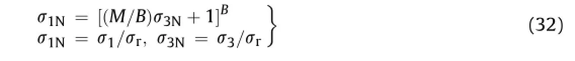
whereσ1andσ3are the principal stresses;M and B are empirical rock parameters related to compressive and tensile strength, respectively,derived from compressive strength as per the JC-criterion.
Upon simpli fi cation of Eq.(32)we get

whereσtis the tensile strength of rock sample.
The Mohr-Coulomb criterion(MC-criterion),one of the most popular strength criteria for geo-materials,is applied reasonably and wellto the rock masses whenσr/σt>10(Labuz and Zang,2012). Interestingly,once B=1,Eq.(32)is reduced to MC-criterion as σ1N=Mσ3N+1,where M=(1+sinφ)/(1-sinφ),in whichφis the angle of internal friction of joint material.
The JC-criterion takes an advantage of inclusion of a ratio of compressive to tensile strength as per Eq.(33)and a ratio of principalstresses(Eq.(32))in the dimensionless form.It considers the ratio of tensile to compressive strength as a material constant which can be readily estimated by standard laboratory techniques. The frictional forces in the micro-joints and micro-crack network modify the ratio as per Eq.(33).The modi fi cation of empiricalrock constants,consequently on the changes in initial isotropic condition and joint conditions,is related to the modi fi ed joint factor.The range of uniaxial compressive and tensile strengths of rocks and rock-like materials varies signi fi cantly upon the intrinsic factors (Carpinteri et al.,2005),which are well considered by modi fi ed joint characteristics.The concentration of stresses tends to extend the failure surface,which in turn changes the stress and volume varying pattern.With the progressive failure,the joint damage occurs which transforms the mean effective con fi ning pressure on the elements under consideration.
Based upon the JC-criterion,a relationship for rock masses is considered as
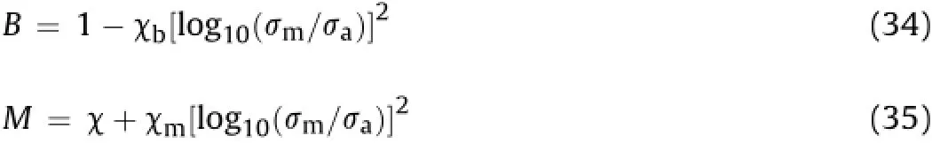
whereσais the reference stress taken as 1 kPa.The values of the empirical constants in Eqs.(32)-(35)are compiled in Table 7.χ,χb, χmare empirical rock constants in JC-criterion.For rock masses having negligibleχm,the value of M tends toχ(=2)as per the JC-criterion.The values ofχbandχmrefer to the gradient in the fi tting linear relationship of B and M with square of logarithmic normalized rock mass strength as shown in Fig.9a and b.
A wide-ranging experimental ratio of compressive to tensile strength obtained by Palchik and Hatzor(2004)on cemented porous chalk and other rocks and rock-like materials(Lama and Vutukuri,1978;Johnston,1985)supports the proposition of linearity of M/B with square of logarithmic normalized rock mass strength as shown in Fig.9c.There is an observed linearity of compressive to tensile strength ratio with crack initiation strength (Perras and Diederichs,2014;Zhao et al.,2015).However, increasing deformation after crack initiation tends to be lognormalized with compressive strength.The parameters of JC-criterion are shown in Fig.9a-c in generalized form.
A great number of empirical data are available for validation of strength theories of rock masses in relation to widely popular Hoek-Brown criterion(HB-criterion)(Hoek and Brown,1980, 1997).The empirical constants associated with HB-criterion for rock masses may be related to the constants used by JC-criterion.
The generalized HB-criterion(Hoek and Brown,1997)for evaluating rock mass strength is represented as

where aHB,mband s are the empirical rock constants as per the generalized HB-criterion for rock masses.The constants of HB-criterion(aHB,mband s)are related to the constants of JC-criterion(M and B)as

Normally the development of strength criterion is based upon a relationship between stress and strain invariants,but under fi eld conditions it is inherently dif fi cult to measure actual stressdeformation fi elds.Therefore,a plastic parameter based upon preliminary observations of dilatancy from different investigators (Table 2)is related to joint characteristics of rock mass as observed in laboratory and fi eld tests.
3.2.Pressure and damage sensitive plastic parameter in relation to the dilatancy
The volume change of rock masses is normally localized due to joints having lower values of joint parameters,namely,modi fi ed joint factor.For higher values of modi fi ed joint factor,the volume changes are well distributed over a larger segment of rock masses. In these circumstances,the average value of volume change is inherently interpretive.Moreover,the joint friction factor does not remain constant during shear.During shear the rock mass may contract or dilate to transform joint parameters as a compressed function of state,namely,magnitude of pressure,compactness of joints,damage or impairment,and material characteristics of gouge,which are dif fi cult to be measured in practice but easier to be interpreted if the concept of pressure sensitive damage and dilatancy is applied to the rock masses.
Based upon the work of Taylor(1948),Rowe(1962),Vesic and Clough(1968),Billam(1972),de Jong(1976)and Bolton(1986) reviewed the stress-dilatancy relation for 17 different sands and proposed an empirical relation for dilatancy of soils,where the angle of dilation isψmax=AbIr,in which Abis an empiricalconstant and has a value of 3 for axisymmetrical and 5 for plane strain conditions.Such that the dilation angle(ψ=φp-φc)is de fi ned as a difference of peak(φp)and critical friction angle(φc)in degree. Accordingly,relative dilatancy is Ir=10(-d3v/d3s)/3 where d3vis the change in volumetric strain in the zone of shear and d3sis the change in shear strain.Ojha and Trivedi(2013)and Xiao et al. (2014)extended this relationship to the volume change characteristics of compacted silty soils and compacted rock fi ll materials, respectively.Walton and Diederichs(2015),based upon the observations of Vermeer and de Borst(1984),related the dilation angle with the ratios of plastic volumetric strain and shear strains to con fi ning pressure for intactrocks.Since Jfgis a function ofplastic volume change(Eqs.(20)and(21)),it is advanced for plasticity and damage of rock masses in relation to empirical fi tting parameter (ξpd)as

Based upon the observations of several investigators(Horne, 1965;Rowe,1969;Akai et al.,1978;Hirai and Sitake,1982;Spitzig and Richmond,1984;Bolton,1986;Santarelli,1987;Besuelle et al.,2000;Vatsala et al.,2001;de Buhan et al.,2002;Stoughton and Yoon,2004;Yuan and Harrison,2004;Castellanza and Nova, 2004;Trivedi,2010,2013a;Noorian-Bidgoli,2014;Perras and
Fig.9.Variation of intact and rock mass parameters.
Diederichs,2014;Li et al.,2015;Walton and Diederichs,2015)on mass materials,the author extended inputs from JC-criterion,and formulated related strength ratio with dilatancy ofrock masses,in a simple form as

whereαp=λ/C,is the modi fi ed joint factor for plasticity and damage.Eqs.(12)and(39)are similar in appearance but differ signi fi cantly in magnitude due to damage.
Similarly,the strength ratio is related to relative dilatancy inclusive of damage as

whereξ=Ab/C.
Ideally,the strength depends upon the number of joints if1 and upon joint factor alone if cg=1.Table 8 provides selected values of coef fi cient of modi fi ed joint factor and dilatancy index with varied end conditions and initial con fi ning pressure.Most often the strain does not remain exactly in plane strain or triaxial condition,but the end conditions allow for in-between values ofαp. The values ofαpandξdepend upon volume change characteristics of rock masses.Interestingly the ranges of their values overlap the zone ofplastic dilatancy ofselected mass materials as also shown in Table 2 and supported by Eqs.(38)-(40).
3.3.Numerical formulation
Consequentto the loading,the volumetric strains of rock masses are set,accompanied by the joint damage due to the changes in the magnitude of cracks,micro-cracks and fracture network which can be modeled for fracturing process in rock masses(Lisjak and Grasselli,2014).The stress redistribution continues till the deformation develops.The in fi nitesimal changes in isotropic pressure (δp)produces irrecoverable volume changeswhich may be due to plasticity and damage.Hence there is an induced potential
where inand jnarrive through a hardening and softening process characterized by a plastic parameter.In the process,the rock mass has a maximum conservative component of the input energy corresponding to the critical value of pressure.The fi nal state of plasticity and damage does have a scope to capture the initial conditions in steps by trial.
It was observed that the incremental potential of isotropic pressure(δi)and incremental potential of joint parameter(δj)infl uence the contraction-expansion,translation and shift in p-q space,which can be represented as

There is one to one mapping of Chscorresponding to the value of<Chs>at micro-mechanical and granular level due to unit changes in the joint damage parameter.The value of C hs for rock masses is obtained by estimating strength with varying effective con fi ning pressure for different isotropic ratios(pi/σr).
It was observed that increasing the pressure ratio up to the critical one(associated withtends to increase the plastic parameter,while beyond this limit,the plastic parameter tends to decrease.A critical pressure ratio is a ratio of pressure at peak softening characterized byαpto that at peak hardening characterized by the peak value of Chs.It permits numerical separation of dominant hardening from that of softening regimes.It is explicitly dif fi cult to know at which pressure either of the hardening or softening offsets each other without using the proposed technique. The solution to Eq.(43)implies an increasing or decreasing intercept on q-axis with increasing con fi nement.An increasing value ofconserves energy so that rock masses appear stronger on yield which is a characteristic of dense granular material(Scho fi eld and Wroth,1968).The effect ofis translational in the p-q space to actuate softening process.The shape and size of p-q plot in Eq.(43) is modi fi ed by the parameter Cijand represented as
The shear stress in Eq.(44)is presented in a simpli fi ed form as
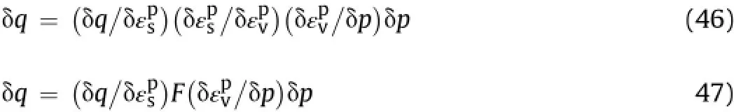
From Eqs.(45)and(49),we have

Eq.(50)gives a pressure-sensitive directional frictional fl ow with consideration of effects of damage and joint parameters.If there is a continued gain or decay in strength due to deformations, either hardening or softening is set into the process,therefore, solutions to Eq.(43)which considers plasticity and yielding amid joints for an assumed frictional fl ow of rock mass can be represented as

whereδA represents a parameter associated with changes in Helmholtz free energy density due to frictional fl ow and joint damage at an ambient temperature normally ignored in the rock

where<hhs>is the joint damage parameter.then<hhs>=1;and ifthen<hhs>>1. In the initial hardening range,Chs→Ch,then Chs=f(pi/σr,αp), which can be expressed as a power function:

The limit values of hardening and softening parameters are listed in Table 10,and the values of constantsκand h used in Eq. (53)are shown in Table 11.
3.4.Discussion of results
As a consequence of these observations,it is understood that softening of resistance to loading and volumetric dilation control the relationship ofσmrand Emr.
The strength of intact cemented and jointed materialspecimens is plotted(Fig.10)from the published data sets(Lama and Vutukuri, 1978;Arora,1987;ACI-318,1995;Ramamurthy,2004;Sonmez et al.,2004;Singh and Rao,2005;Chun et al.,2009)for modulus of deformation as
where aγand aγmare constants of proportionality showing effects of unit weight and strain level on rock masses,respectively;d and dmare the fi tting exponents which depend upon softening due to the dilation of intact rock and rock masses from the passage of initial tangency to an eventual failure:

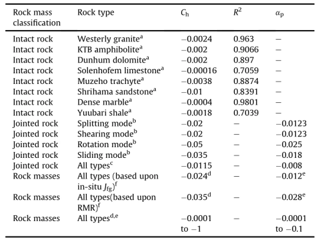
Table 10 Limit values of hardening and softening parameters.
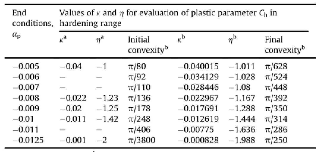
Table 11 Constants used for calculation ofplastic parameter Chin hardening range.
where dmris a fi tting exponent which varies according to the relative dilation of rock mass compared to that of intact rock.If aγm=aγ,thenσmrTable 9 shows values of dmrcomputed from the available data sets of several investigators along with the determination coef fi cients.
As per the empirical estimates shown in Table 9,dmrnormally takes a value from 1 to 0.4.
In fact,Eq.(56)provides an empirical estimate for the relationship between strength and modulus ratio without consideration of joint contraction and dilation(Fig.10).
3.5.A relationship ofσmrvs.Emrbased upon pressure and damage sensitive plastic parameter,joint parameters and RQD
The typicalshear-volume change characteristics of jointed rocks under mechanical loading are shown in Fig.1.The observations of the volumetric response of rock masses are summarized(Table 2) as follows:(1)The mass materials can be characterized in a relatively intact(strong)and a fully mobilized(weak)state where the strength can be lower than that obtained at the critical state,as postulated in DSC.(2)Irrespective of the magnitude of the con fi ning pressure and joint conditions,there exists an initialphase of linear contraction which is characterized by“hardening”effects. (3)The bigger grains and intact block show crack initiation and damage.(4)Hardening begins initially and continues to offset damage and softening up to a critical(saddle)pressure.(5)Further increasing pressures lead to dilation and damage occurring after contraction effects.(6)The higher the con fi ning stress applied is, the less the degree of dilation and damage that occurs in the hardening regime is.(7)As the peak load is reached,deformation becomes localized along oriented paths,and disintegrates progressively to collapse.(8)The“softening and damage”produce a path speci fi c drop in resistance and cause the resistance of surrounding rock following a pressure gradient.
As Eqs.(12)and(13)and Eqs.(14)and(15)provide a relation-respectively,Eqs.(29)-(31) connect modi fi ed joint factor,joint factor and joint number with RQD,respectively.As a result,the strength ratio is shown to depend upon RQD.
There are two ways to validate such a relationship indirectly.As most of the available data of in-situ testing are captured,not necessarily,at the arrival of failure,σmrvs.RQD relationship is validated using the available data set of Emrvs.RQD and by evaluatingσmrusing empirical relationship ofσmrvs.Emr(Eqs.(56)and (60)).Secondly,utilizing the fi nal value ofσmrfrom RQD,corresponding to the end values ofαp(Eqs.(12)and(13))using empirical fi tting coef fi cients a and b for modi fi ed joint factor and RQD relationship(Eq.(29)).
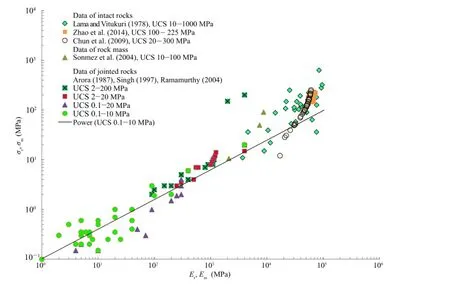
Fig.10.Variation of compressive strength and modulus at varied strength levels.
However,since the sensitivity to damage is not considered in Eqs.(12),(13),(19)and(56),a parameter,ζ,is adopted for inclusion of damage.
The strength ratio(σmr)and modulus ratio(Emr)in hardening range are associated with the ampli fi cation factorapplied on peak hardening strain of rock mass and,respectively,to provide a plastic strain ratiofor the rock masses as
The modulus ratio is related to observations of modi fi ed joint factor in hardening range,similar to the relationship between strength ratio and modi fi ed joint factor in softening range.Therefore,it is convenient to propose a relationship between strength ratio and modulus ratio incorporating a pressure-dependant plastic parameter.Hence,we have
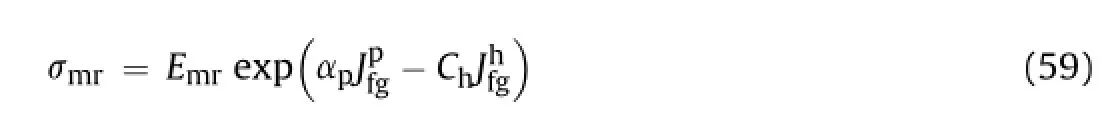
The experimentally observed values of hardening parameter Chof intact and jointed rock masses are shown in Table 10.Table 11 shows the range of observed and computed values of Ch.As the change in modi fi ed joint factor is signi fi cant during hardening and softening processes,Eq.(59)becomes
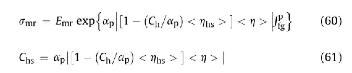
where|[1-(Ch/αp)<hhs>]<h>|=ζis a pressure and damage sensitive plastic multiplier,which takes only positive values, otherwise it violates the laws of thermodynamics.A critical pressure ratio at a saddle pressure is a ratio of pressure at peak softening to that at peak hardening.It allows numericalseparation of dominant hardening from that of softening regimes with the help of two more plastic parameters,namely,<hhs>and<h>.<hhs>and<h>are also plasticity and damage sensitive parameters such that they allow a transition betweenThe nature of parameter<h>is the signum function unde fi ned at zero.It is a function ofapplied pressure and takes a value of±1 while changing its sign as the state of stress is greater than the saddle pressure. Furthermore,<h>differentiates sensitivity of this parameter such that<h>=±1,as either hardening or softening takes place.Since<h>≠0,it implies that the work done is essentially nonconservative.Similarlyζimplies that there is a functional relation between the plastic multiplier and damage parameter.The effect of variation ofplastic parameter Chs(at values of<hhs>=0.1,1,10,100 and 1000)with increasing pressure ratio is shown in Fig.11.
Fig.11 shows that the saddle pressure increases sharply if the joint damage parameter<hhs>>>0.1,as summarized in Fig.12. Fig.13 shows the variation of ampli fi cation factor with joint damage parameter.An important outcome of the study is to fi nd a pressure at which softening starts dominating the hardening process.The peak hardening pressure is obtained from the pressure of peak hardening shown in Fig.11,and presented in Figs.12 and 13.
Corresponding to the plastic parameter,per unit changes in the joint damage parameter Chs,a variant of plastic parameter<Chs>, are de fi ned as

The minimum value of<Chs>would attain a non-zero value (?<0),while the maximum value would correspond to the peak hardening.
From Eqs.(57)-(62),we have

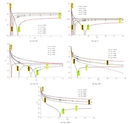
Fig.11.Variation of plastic parameter with con fi ning pressure ratio at different values of<hhs>.
The joint damage parameter(<hhs>)implies deterioration of the rock mass condition ever since the pressure increases beyond the peak hardening pressure,while<Chs>is a variant of plastic parameter per unit change in the joint damage parameter.Fig.14 demonstrates the variation of<Chs>with pressure ratio for varied end conditions and joint damage parameters.Fig.14 shows the intermediate stages in the evolution of the parameter Chswith incremental damage as per the increasing values of the damage parameter,<hhs>at the arrival of shear fl ow.
Based upon the observations(Bieniawaski,1978;Chun et al., 2009;Coon and Merritt,1970;Ebisu et al.,1992;Isik et al.,2008; Labrie et al.,1997;Vukovic,1998;Yang,2006)Fig.15 shows indirect interpretation ofσmrvs.RQDrelation using the empiricalrelationship ofσmrvs.Emrat dmr=0.5 and 1,respectively.The effect of plasticity and damage on RQDhas been considered through a parameter Chs(at values ofζ=0.5,1,2,and 5)as shown in Fig.16.Fig.16 shows indirect validation from in-situ data.It provides a relation to obtainσmrvs. RQD with consideration of softening and damage.
It would be appropriate to de fi ne the similarity between the two ways of indirect validation.Both the methods estimate the value of strength ratio,but the estimate shown in Fig.15 is obtained by the crude empiricaltechnique based upon power law while that shown in Fig.15 is supported by in-situ empirical data.One of the strong supports for this validation is the data fi tting corresponding to theempirical observation in Fig.15a which closely follows one of the observations plotted in Fig.16a.
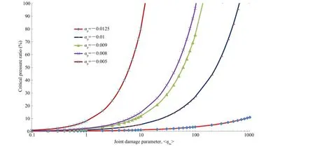
Fig.12.Variation of critical pressure ratio with joint damage parameter.
The data ofσmrplotted in Fig.16a and b do not necessarily represent the peak strength.From the small scale testing and insitu measurements,they relate the deformation and strength of rock mass as ideally shown in Eqs.(38)-(40)through the use of damage sensitive plastic parameter.
Therefore,utilizing the relationship of joint mapping through damage and pressure sensitive characteristics in hardening and softening ranges(Eq.(59)),the strength ratio is expressed as

By applying and utilizing Eq.(29),the rock mass strength ratio is expressed in terms of the plastic parameter and RQD as

where a=1000 and b=-1 to-0.01,depending upon joint characteristics.
Eqs.(64)and(65)provide a relationship to obtain the strength based upon pressure dependent softening and damage.The values of Emrandσmrevaluated from in-situ observations are presented in Tables 12 and 13.
Therefore,using Figs.15 and 16,the strength ratio may be expressed as an exclusive function of RQD:

where m and n depend upon the pressure and damage sensitivities of rock masses.The damage and pressure sensitivities as per the selected data set are shown in Tables 14 and 15,which show varied levels of initial plasticity quanti fi ed through n.If the block obtained from a core recovery sample is less than 10 cm in length,the RQD value sets to zero.As RQD=0,log10RQD reaches singularity,it cannot be de fi ned.Therefore,the strength ratio canbe evaluated by obtaining the modi fi ed joint factor.To evaluate the strength ratio at RQD=1,since log10RQD=0,σmr=n in Eq. (66).In fact,n can be fi ne adjusted as a function of modi fi ed joint factor(Table 16).
Fig.13.Variation of ampli fi cation parameterwith joint damage parameter.
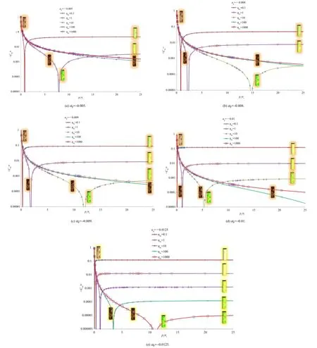
Fig.14.Variation of plastic parameter with con fi ning pressure ratio for varied joint damage parameters at different end conditions.
As RQD→0,Eq.(66)has constants(m and n)and the strength may be obtained by statistical extrapolation.For evaluating the strength corresponding to RQD→0,there are a wide-ranging values of Jfgassociated with varied site stress condition,plasticity and damage at speci fi c pressure conditions as shown in Fig.6.
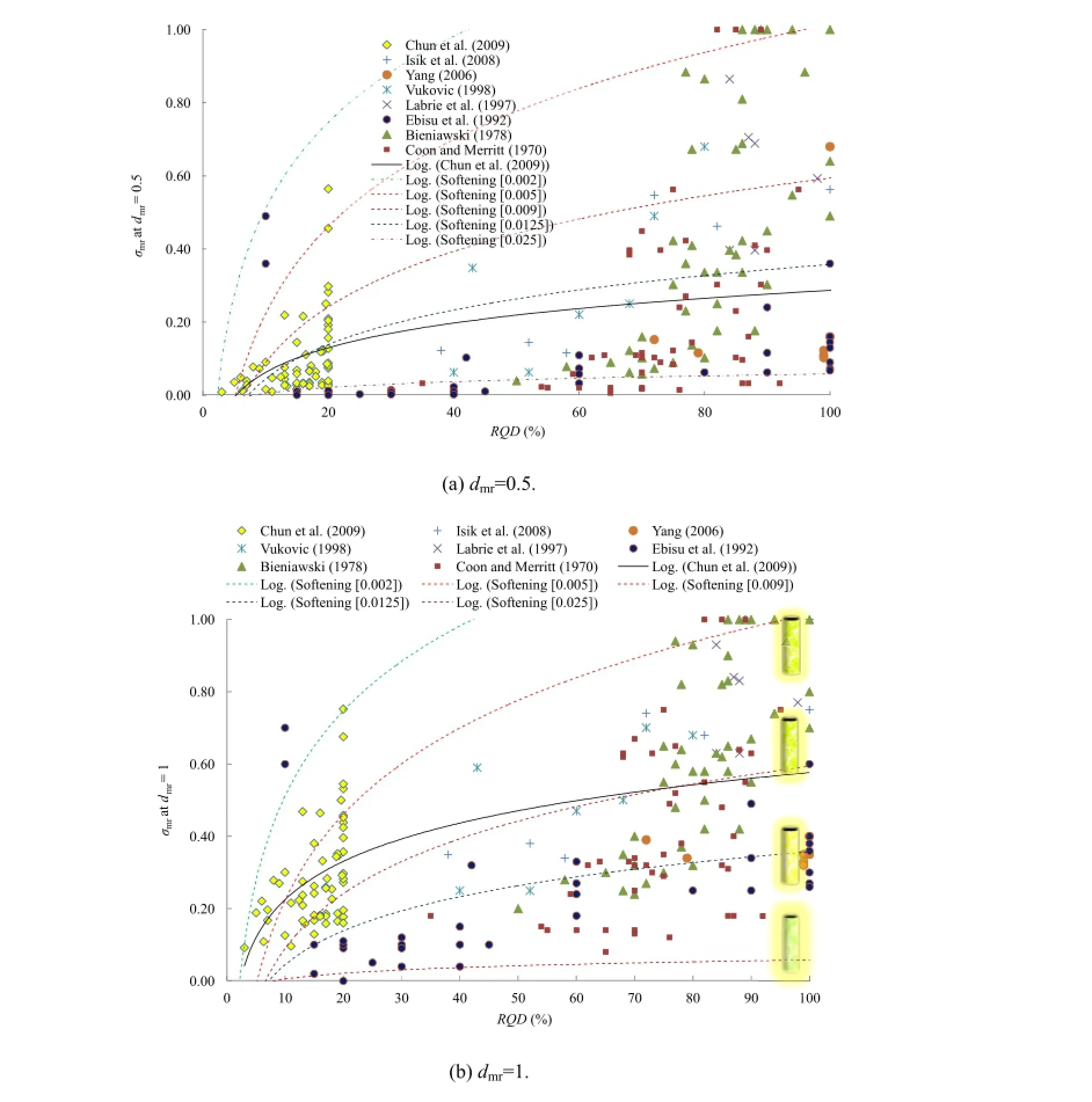
Fig.15.Indirect validation of relationship ofσmrvs.RQD.Data points are obtained by→0 in Eq.(9)and different values of dmr;dotted lines are obtained byαp=-0.002 to-0.025 with reference to the best fi t with the power law.
The relationship proposed in Eq.(66)is further supported by the back calculated data of RQD shown in Fig.17 which deterministically quantify the initial plasticity and damage through rock mass parameters considered in the modi fi ed joint factor vs. RQD relation.
Fig.17 provides a validation for the theoretical relationship of RQD and strength ratio in a generalized form,taking plasticity and damage into consideration(αpandζ)at varied levels ofaccumulated plastic strains characterized by the rock mass parameter b.Fig.17d shows indirect validation of the theoretical relationship shown in Fig.17a-c using calculated data of RQDand mobilized strength ratio in the hardening range obtained from in-situ data.Fig.17e shows direct validation of the theoretical relationship shown in Fig.17a-c using back calculated data of RQD and mobilized strength ratio in the softening-damage range obtained from laboratory tests.
Based upon the in-situ observations of strengthcorresponding to a RQD value in two most probable states of strength, namely,the minimumstrength ratios, an index of progressive failure(Im)is de fi ned as

where Mrqdis the slope of linear fi tting obtained from Imvs.RQD observation.
The index of progressive failure(Im)is obtained from the values of the minimumstrengths from plasticity and damage sensitivities of rock masses.An example of the index of progressive failure observed in the laboratory and in-situ test is shown in Fig.18.The value of Mrqddepends upon the nature and extent of inherent and induced discontinuities in the rock mass.Therefore,for each data set,Mrqdcan be statistically obtained,M rqdshows proximity of individual data point to the anticipated progressive failure of the data set.This indicates that fullmobilization of strength exists while it is negligible when the index tends to zero.It can be observed thatthe maximumstrength is mobilized for RQD as low as 20%for the selected in-situ test data.
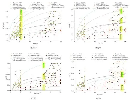
Fig.16.Indirect validation of relationship ofσmrvs.RQD.Data points are obtained by→0 in Eq.(64)and different values ofζ;dotted lines are obtained forαp=-0.002 to-0.025 with reference to the best fi t.
4.Steps for implementation of present technique
The following steps may be considered to implement the present technique:
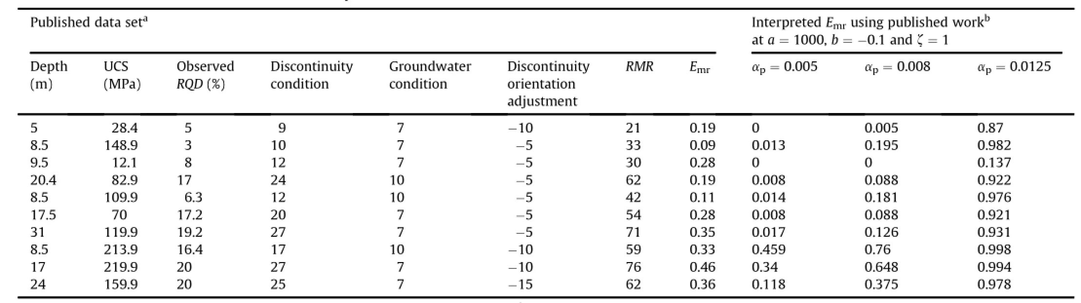
Table 12 In-situ modulus ratio of rock masses evaluated from published data set.
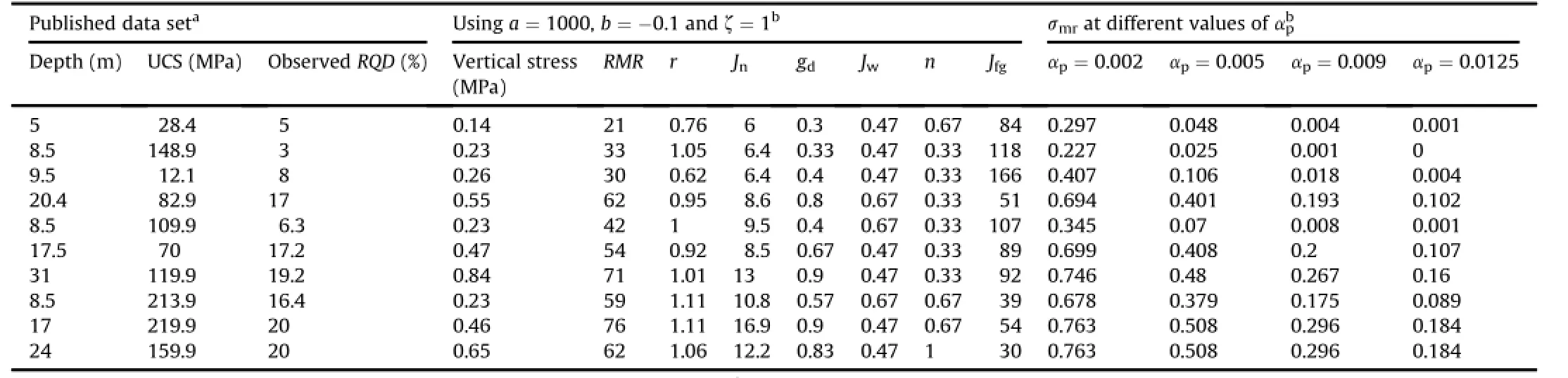
Table 13 In-situ strength ofrock masses evaluated from published data set.
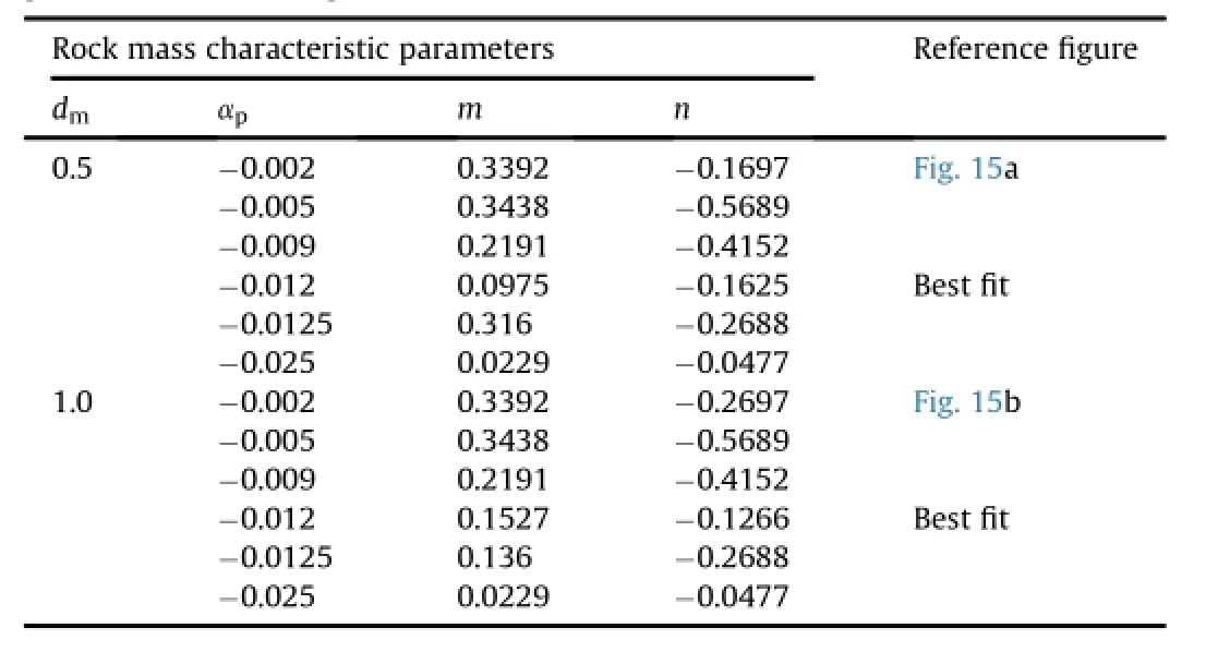
Table 14 Evaluation of in-situ strength of rock masses from RQD in Eq.(66)usingσmr-Emrpower law relationship.
(1)Identify important information to be included in bore log data sheet,namely depth of sample collection at requisite intervals; unit weight;overburden pressure;joint number;inclination of joints and orientation parameter;joint condition;the maximum,minimum and mean thickness of gouge;density ofgouge;frictional properties;water pressure and RQD.Additional parameters for inputs of RMR,GSI,and Q-system may also be considered.
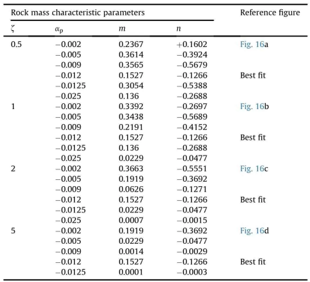
Table 15 Evaluation of in-situ strength of rock masses from RQD using Eq.(66)using parameterζ.
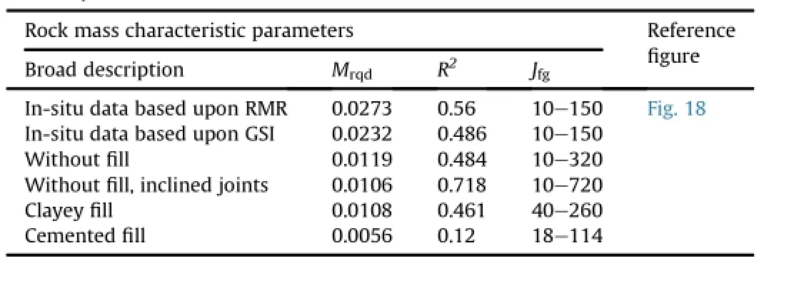
Table 16 Index of progressive failure of rock masses from RQD in Eqs.(67)and(68)using Im=MrqdRQD.
(2)Evaluate the values of Jfg,αp,Ch,Chs,and<Chs>in the spread sheet using Eqs.(10)and(11),(13),(15),(61)and(62), respectively.An example to calculate modulus and strength ratio using joint parameters evaluated from in-situ data of RQD is shown in Tables 12 and 13,respectively.
(3)Consider Eqs.(36),(38)-(40),inputs of Jfg,con fi ning pressure and n to obtain a value ofαp.
(4)Evaluate the overburden and con fi ning pressure,and consider Chaccording to the values ofαp.
(5)Draw a plot between the modi fi ed joint factor and RQD to fi nd out the parameter b(Eq.(21)).
(6)According to the values ofαpand b,fi nd out the value ofσmrfrom RQD(for example Fig.17a-c).
(7)Estimate values of Chs(Fig.11)for an appropriate value of<hhs>and pressure.
(8)Operate Chsat an appropriate pressure upon RQD to getσmrat any in-situ hardening and softening as well damage consideration shown in Fig.17d and e,respectively.
(9)Obtain the index of progressive failure as per Eqs.(67)and(68) for the entire length of scan line of RQD.
5.Scope of application of the present model
The plastic parameter captures the available data set of strength ratio obtained from RQD and laboratory testing using the present technique.The strength criterion used herein provided a data set in normalized form for the application ofthis technique.The relations described above should be judiciously applied with the following reasons:
(1)The strength criterion cited in the paper is essentially empirical
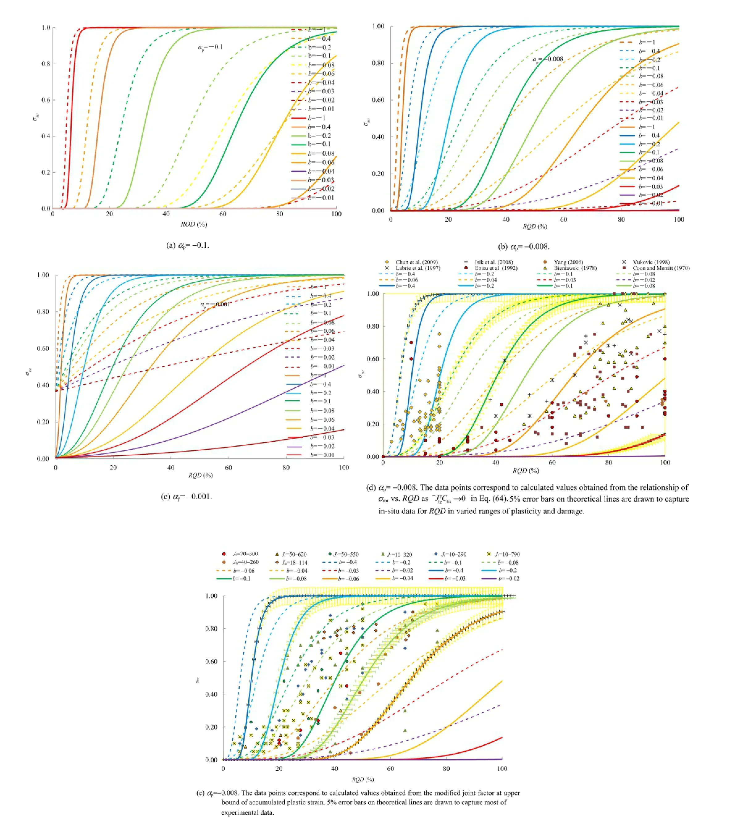
Fig.17.Theoreticalvariation ofstrength ratio with RQD using the pressure and damage sensitive plastic parameterζ=1,5 and differentαp,implying their effects on varied levels of accumulated plastic strains identi fi ed by b-values.The effect of plasticity and damage is presented by the solid lines,and the effect of plasticity is shown by the dotted lines.
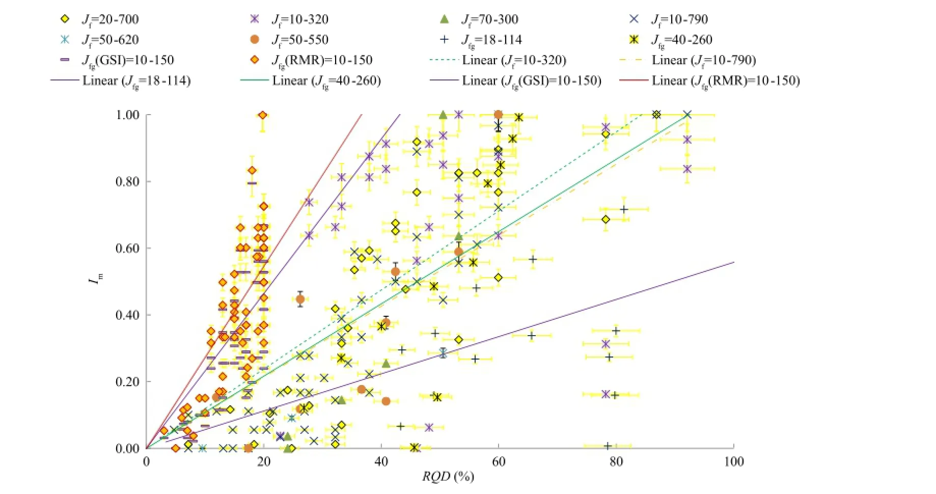
Fig.18.Index ofprogressive failure obtained from in-situ tests and laboratory data ofstrength ratio vs.modi fi ed jointfactor.RQD is obtained from the modi fi ed jointfactorvs.RQD relationship at the maximum accumulated plastic strain with and without gouge shown by solid and dotted lines,respectively,along with 5%error bars.
and the constants associated with various relationships(shown in Tables 4 and 5)provide an approximate interpretation of strength.The empiricalstrength criteria,namely,MC-criterion, HB-criterion,and JC-criterion,were initially proposed with idealization and they were extended later to rock masses.
(2)The strength of rock masses depends upon intact rock strength, joint parameters(represented by the modi fi ed joint factor), plastic volume change and damage characteristics.
(3)The range of strength ratio is essentially from 0 to 1.The strength ratio of 1 represents the strength of intact rocks.Occurrences of joints,decreasing size,and damage increase the modi fi ed joint factor,which is observed in a range of 1000-0. The zero value of modi fi ed joint factor may correspond to the strength of intact rock.
(4)In-situ characterization of rock masses is carried out by borehole-log-data(to provide the value of modi fi ed joint factor)and RQD.RQD is observed in a range of 0-100.The zero value of RQD is associated with heavily jointed rock masses. There exists an exponentialrelation between the modi fi ed joint factor and RQD based upon the in-situ data characterized by a fi tting parameter b(Fig.8).
(5)The plastic volume change characteristics consist of dominant hardening at relatively lower pressures and softening as a dominant process at higher pressures.
(6)This work applies concepts of progressive stiffness and degradation using a pressure and damage sensitive plastic parameter. The process used for the development of the present criterion is one of pure trial-and-error and of numerical implementation.
(7)The hardening fi rst increases with isotropic pressure and then softening and damage appear as an effectofincreasing isotropic pressure.The process from hardening to softening is continuous.As a result,the plastic parameter can be used to show the critical point between hardening and softening.Hence,the plastic parameter beyond the peak hardening is a value approaching the peak softening with plastic volume changes, shear and damage.
(8)The volume change of rock mass has a nonlinear relation with the strength.The laboratory estimated values of plastic and damage parameter can be extended for in-situ evaluation of strength and accumulated plastic strains adjusted for the laboratory and fi eld data.The precise predictions of strength of rock masses depend upon an appropriate choice of plastic and joint damage parameters.As a result,there can be several possible combinations of rock mass parameters,namely,b,Chs, αpandζcorresponding to a particular RQD which may provide the same strength ratio.
(9)Similar to the current trends in modeling,the present work intends to arrive at an appropriate level of plasticity and damage based upon selection of joint parameters.The purpose of this technique is to provide a framework to obtain a plastic parameter isolating damage in relation to strength and RQD and to fi nd it using a simple numericaltool.An index of progressive failure can be obtained from the in-situ observations of RQD.
6.Conclusions
This paper is based upon the current trends in modeling which does not necessarily predict exact values of in-situ strength of rock masses but brings out a methodology for more rationalestimates of strength of rock masses with the consideration of pressure and damage sensitive plasticity using results of laboratory and in-situ testing.It further presents an argument in favor of wholeness in the behavior of rock masses such that the strength ratio drops below the one as the damage and plasticity are introduced into the mass material as an effect of induced pressure.The trends in strength criterion and rock mass characterization techniques(RMR, GSI and Q-system)may not essentially capture altogether the contraction,dilation and damage sensitivities of joints,fractures and micro-crack network with reference to in-situ and laboratory estimates so well as the present proposal.
The relationships between intrinsic joint parameters and the isotropic pressure provide inputs for a numerical technique to incorporate these effects into the strength ratio.The results of the present work show that variability between laboratory testing and in-situ testing results is essentially due to the plasticity,damage and the accompanying changes in the joint parameters characterized by accumulated plastic strains.This technique considers the effect of a damage sensitive plastic parameter on strength by initialand end conditions of the parameter of readily estimated modi fi ed joint factor and wellrecognized RQD for rock masses.The published data relating the modulus ratio with RQD and the strength ratio with the modi fi ed joint factor provide a scope for validation of present proposal and to obtain strength ratio.The recognition of intrinsic joint characteristics in relation to the pressure and damage sensitive plastic parameter provides a resolution to the multiplicity in interpreting the in-situ strength of rock masses.
Con fl ict of interest
The author would like to af fi rm that there is no known con fl ict of interest associated with this publication,as there was no signi fi cant funding for this work from any sponsoring agency,which could in fl uence the fi nding of this study.
Acknowledgments
The author is thankful to several data sources,meaningful inputs from coworkers and editors for their suggestions in improving this paper.
Notations
AbEmpirical constant which takes a value 3 for axisymmetrical and 5 for plane strain case as per Bolton (1986).
δA Parameter associated with changes in Helmholtz free energy density
a,b Fitting parameters for experimental data of RQD and modi fi ed joint factor
aγ,aγm,d,dm,dmrFitting constants and exponents for experimental data of strength and modulus of rocks and rock type masses
aHB,mb,and s Empirical rock constants as per the generalized HB-criterion
C,C'lastic parameters
Ch,Chs,<Chs>Variants of plastic parameter
<h>Signum function which takes a value±1
<hhs>Joint damage parameterModi fi cation factor for joint number and joint factor, respectively
αpObserved parameter depending upon pressure and joint characteristic dependent softening
Er,EmModulus of intact rock and rock mass,respectively
F Flow function
IrRelative dilatancy index
?,?Limit values for variation of softening parameters such that?>Chs>?
i Potential for change in isotropic pressure with plastic volumetric strain
j Potential for change in plastic shear strain with shear stresses
Jt,Jdj,JwFactors for joint thickness,depth,ground water conditionJoint factor and modi fi ed joint factors respectively Modi fi ed joint factors in hardening and softening range, respectivelyModi fi ed joint factor due to plasticity and damage Number of joints in the direction of loading per unit length
LnaReference length=1 m
M and B Empirical rock parameters depending upon compressive strength as per the JC-criterion
χ,χb,χmEmpirical rock constants in JC-criterion nβJoint orientation parameter depending upon inclination of the joint plane(β)with respect to the direction of loading
p andδp Mean effective con fi ning pressure and its change, respectively
piInitial mean con fi ning pressure
q andδq Shear stress and its change,respectively
r Reference joint strength parameter
RMR,Q,GSI,MC,JC,HB Rock mass rating,Q-system,Geological strength index,MC-criterion,JC-criterion and HB-criterion,respectively
RDRelative density of gouge
RQD Rock quality designation
λand C Empirical parameters for dilatancy of jointsHardening strains of intact rock,rock mass and hardening strain ratioPlastic strain ratio of rock mass and intact rock Plastic volumetric strain and plastic shear strain, respectivelyStress multiplication factors for hardening of intact rock,rock mass,and rock mass stress ratio to reach full plastic state ζDamage sensitive plastic multiplier
σ1,σ2,σ3Principal stresses in the intact rock
σ1m,σ2m,σ3mPrincipal stresses in the rock mass
σ1N,σ3NPrincipal stress ratios used in the JC-criterion,σ1N=σ1m/ σrandσ3N=σ3m/σr
σr,σmUniaxial compressive strength of intact rock and rock mass,respectively
σaReference stress,σa=1 kPa
σmr,EmrStrength ratio and modulus ratio,respectively
Λi,Λj
ACI Committee 318.Building code requirements for structural concrete(ACI 318M-95)and commentary(ACI 318RM-95).Farmington Hills,USA:American Concrete Institute;1995.
Akai K,Adachi T,Nishi K.Elasto-plastic behavior of soft sedimentary rock(porous tuff).Proceedings of the Japan Society of Civil Engineers 1978;271:83-95.
Al-Ajmi AM,Zimmerman RW.Relation between the Mogi and the Coulomb failure criteria.International Journal of Rock Mechanics And Mining Sciences 2005;42(3):431-9.
Aldrich MJ.Pore pressure effects on Berea sandstone subjected to experimental deformation.Geological Society of America Bulletin 1969;80(8):1577-86.
Arioglu N,Girgin Z,Arioglu E.Evaluation of ratio between splitting tensile strength and compressive strength for concretes up to 120 MPa and its application in strength criterion.ACIMaterials Journal 2006;103(1):18-24.
Arora VK,Trivedi A.Effect of Kaolin gouge on strength of jointed rocks.In:Rock Slopes:Proceedings of the Asian Regional Symposium 1992.New Delhi:CRC Press;1992.p.21-5.
Arora VK.Strength and deformation behavior of jointed rocks.PhD Thesis.Delhi, India:Indian Institute of Technology;1987.
Barton N.Deformation phenomena in jointed rock.Geotechnique 1986;36(2):147-67. Barton N.Shear strength criteria for rock,rock joints,rock fi ll and rock masses: problems and some solutions.Journal of Rock Mechanics and Geotechnical Engineering 2013;5(4):249-61.
Barton N.Some new Q-value correlations to assist in site characterization and tunnel design.International Journal of Rock Mechanics and Mining Sciences 2002;39(2):185-216.
Besuelle P,Desrues J,Raynaud S.Experimentalcharacterization of the localisation phenomenon inside a Vosges sandstone in a triaxial cell.International Journal of Rock Mechanics and Mining Sciences 2000;37(8):1223-37.
Bieniawski ZT.Determining rock mass deformability:experience from case histories.International Journal of Rock Mechanics and Mining Sciences and Geomechanics Abstracts 1978;15(5):237-47.
Billam J.Some aspects of the behaviour of granular material at high pressures.In: Parry RHG,editor.Stress-strain behaviour ofsoils.London:G T Foulis&Co.Ltd.; 1972.p.69-80.
Bolton MD.The strength and dilatancy of sands.Geotechnique 1986;36(1):65-78. BortolottiL.First cracking load ofconcrete subjected to direct tension.ACIMaterials Journal 1991;88(1):70-3.
Bortolotti L.In fl uence of concrete tensile ductility on compressive strength of con fi ned columns.Journal of Materials in Civil Engineering 1994;6(4):542-63.
Brook N.Estimating the triaxial strength of rock.International Journal of Rock Mechanics and Mining Sciences and Geomechanics Abstracts 1979;16(4):261-4.
Brown ET,Trollope DH.Strength of models of jointed rock.Journal of the Soil Mechanics and Foundations Division,ASCE 1970;96(SM2):685-704.
Brown ET.Strength of models of rock with intermittent joints.Journal of the Soil Mechanics and Foundations Division,ASCE 1970;96(6):1935-49.
CarpinteriA,Cornetti P,Puzzi S.Size effectupon grained materials tensile strength: the increase of the statistical dispersion at the smaller scales.Theoretical and Applied Fracture Mechanics 2005;44(2):192-9.
Castellanza R,Nova R.Oedometric tests on arti fi cially weathered carbonatic soft rocks.Journal of Geotechnicaland Geoenvironmental Engineering 2004;130(7): 728-39.
CEB-FIP Model Code.ComitéEuro-International du Béton.Information Bulletin No. 213-214.1990.http://dx.doi.org/10.1680/ceb-fi pmc1990.35430.URL:,http:// www.icevirtuallibrary.com/content/book/100121.
Chun BS,Ryu WR,Sagong M,Do JN.Indirect estimation of the rock deformation modulus based on polynomial and multiple regression analyses of the RMR system.International Journal of Rock Mechanics and Mining Sciences 2009;46(3):649-58.
Coon RF,Merritt AH.Predicting in situ modulus of deformation using rock quality indices.In:Determination of the in situ modulus of deformation of rock. Philadelphia,USA:American Society for Testing and Materials(ASTM);1970. p.154-73.
de Buhan P,Fréard J,Garnier D,Maghous S.Failure properties of fractured rock masses as anisotropic homogenized media.Journal of Engineering Mechanics 2002;128(8):869-75.
de Jong G.Rowe’s stress dilatancy relation based on friction.Geotechnique 1976;26(3):527-34.
Deere DU,Deere DW.The rock quality designation(RQD)index in practice.In:Rock classi fi cation systems for engineering purposes,ASTM-STP 984.Philadelphia, USA:ASTM;1988.p.91-101.
Deere DU,Hendron AJ,Patton FD,Cording EJ.Design of surface and near surface construction in rock.In:Fairhurst C,editor.Failure and Breakage of Rock,8th Symposium on Rock Mechanics.American Institute of Mining,Metallurgical and Petroleum Engineers;1967.p.237-302.
Desai CS.Constitutive modeling of materials and contacts using the disturbed state concept:Part 1-Background and analysis.Computers and Structures 2015a;146:214-33.
Desai CS.Constitutive modeling of materials and contacts using the disturbed state concept:Part 2-Validations at specimen and boundary value problem levels. Computers and Structures 2015b;146:234-51.
Drucker DC,Prager W.Soilmechanics and plastic analysis or limit design.Quarterly of Applied Mathematics 1952;10(2):157-65.
Drucker DC.A de fi nition of stable inelastic material.Journal of Applied Mechanics 1959;26:101-6.
Ebisu S,Aydan O,Komura S,Kawamoto T.Comparative study on various rock mass characterization methods for surface structures.In:Hudson JA,editor.ISRM Symposium:EUROCK’92,Rock Characterization.London,UK:Thomas Telford Ltd.;1992.p.203-8.
Eid HT.A technique for estimating permeability ofa randomly fractured rock mass. Acta Geotechnica 2007;2(2):97-102.
Einstein HH,Hirschfeld RC.Model studies on mechanics of jointed rock.Journal of the Soil Mechanics and Foundations Division,ASCE 1973;99(3):229-48.
F?rster S,Plantenberg T.From self-organizing polymers to nanohybrid and biomaterials.Angewandte Chemie International Edition 2002;41(5):688-714.
Grenon M,Hadjigeorgiou J.Evaluating discontinuity network characterization tools through mining case studies.In:Soil Rock America 2003,vol.1;Boston,2003. p.137-42.
Herrmann HJ,Kertész J,de Arcangelis L.Fractal shapes of deterministic cracks. Europhysics Letters 1989;10(2):147-52.
Herrmann HJ,Roux S.Statistical models for the fracture of disordered media. Amsterdam,Netherlands:North-Holland,1990.
HiraiH,Satake M.Proposalofa yield function and description ofplastic behaviorofsoft rocks.Proceedings of the Japan Society of Civil Engineering 1982;320:159-64.
Hoek E.Strength of jointed rock masses.Geotechnique 1983;33(3):187-223.
Hoek E,Brown ET.Empirical strength criterion for rock masses.Journal of Geotechnical Engineering 1980;106(9):1013-35.
Hoek E,Brown ET.Practicalestimates ofrock mass strength.International Journalof Rock Mechanics and Mining Sciences 1997;34(8):1165-86.
Hoek E,Diederichs MS.Empirical estimation of rock mass modulus.International Journal of Rock Mechanics and Mining Sciences 2006;43(2):203-15.
Hoek E,Martin CD.Fracture initiation and propagation in intact rock-A review. Journal of Rock Mechanics and Geotechnical Engineering 2014;6(4):287-300. Horne MR.The behaviour of an assembly of rotund,rigid cohesionless particles, Parts I and II.Proceedings of the Royal Society of London.Series A,Mathematicaland Physical Sciences 1965;286:62-97.
Horpibulsuk S,Miura N,Bergado DT.Undrained shear behavior of cement admixed clay at high water content.Journal of Geotechnical and Geoenvironmental Engineering 2004;130(10):1096-105.
Innocenzi P,Malfatti L,Falcaro P.Water droplets to nanotechnology:a journey through self-assembly.Cambridge,UK:Royal Society of Chemistry;2013.
Isik NS,Doyuran V,Ulusay R.Assessment of deformation modulus of weak rock masses from pressuremeter tests and seismic surveys.Bulletin of Engineering Geology and the Environment 2008;67(3):293-304.
Jain NK.Effect of cemented fi ll on strength of jointed specimen.MS Thesis.Delhi, India:Department of Civil Engineering,Delhi University;2011.
Johnston I,Chiu H.Strength of weathered Melbourne mudstone.Journal of Geotechnical Engineering 1984;110(7):875-98.
Johnston I.Strength of intact geomechanical materials.Journal of Geotechnical Engineering 1985;111(6):730-49.
Kalamaras GS,Bieniawski ZT.A rock strength concept for coalseams incorporating the effect of time.In:Proceedings of the 8th International Congress on Rock Mechanics(Vol.1),Tokyo,Japan.Rotterdam and Brook fi eld:A.A.Balkema; 1995.p.295-302.
Labrie D,Plouffe M,Haevey A,Major C.Distress blast testing at sigma mine: experimentation and results.Div.Rep.No.MMSL 97-143E.Ottawa,Canada: Mining and Mineral Sciences Laboratories;1997.
Labuz J,Zang A.Mohr-Coulomb failure criterion.Rock Mechanics and Rock Engineering 2012;45(6):975-9.
Lama RD,Vutukuri VS.Handbook on mechanical properties of rocks.Clausthalzeller fi eL,Germany:Trans.Tech.Publications;1978.
Li G,Liu Y,Dano C,Hicher P.Grading-dependent behavior of granular materials: from discrete to continuous modeling.Journal of Engineering Mechanics 2015;141(6).04014172.
Lisjak A,Grasselli G.A review of discrete modeling techniques for fracturing processes in discontinuous rock masses.Journal of Rock Mechanics and Geotechnical Engineering 2014;6(4):301-14.
Luding S.Towards dense,realistic granular media in 2D.Nonlinearity 2009;22(12): R101-46.
Martin CD,Kaiser PK,McCreath DR.Hoek-Brown parameters for predicting the depth of brittle failure around tunnels.Canadian Geotechnical Journal 1999;36(1):136-51.
McClintock FA,Irwin GR.Plasticity aspects of fracture mechanics.In:Fracture toughness testing and its applications.Philadelphia,USA:ASTM;1965.p.84-113.
McLamore R,Gray KE.The mechanical behavior of anisotropic sedimentary rocks. Journalof Engineering for Industry 1967;89(1):62-73.
Nicholls K.Discussion on‘Measurement of total core recovery;dealing with core loss and gain’.Quarterly Journal of Engineering Geology and Hydrogeology 2012;45(3):391.
Nicholson GA,Bieniawski ZT.A nonlinear deformation modulus based on rock mass classi fi cation.International Journal of Mining and Geological Engineering 1990;8(3):181-202.
Noorian-Bidgoli M.Strength and deformability of fractured rocks.PhD Thesis. Stockholm,Sweden:Royal Institute of Technology(KTH);2014.
Ojha S,Trivedi A.Shear strength parameters for silty-sand using relative compaction.Electronic Journalof Geotechnical Engineering 2013;18:81-99.
Palchik V,Hatzor YH.The in fl uence of porosity on tensile and compressive strength ofporous chalks.Rock Mechanics and Rock Engineering 2004;37(4): 331-41.
Palmstorm A.Measurements of and correlations between block size and rock quality designation(RQD).Tunnelling and Underground Space Technology 2005;20(4):362-77.
Palmstrom A.Characterizing rock masses by the RMifor use in practical rock engineering:Part 1:the development of the Rock Mass index(RMi).Tunnelling and Underground Space Technology 1996;11(2):175-88.
Perras MA,Diederichs MS.A review of the tensile strength of rock:concepts and testing.Geotechnical and Geological Engineering 2014;32(2):525-46.
Priest SD,Hudson J.Discontinuity spacing in rock.International Journal of Rock Mechanics and Mining Sciences and Geomechanics Abstracts 1976;13:135-48.
Ramamurthy T,Arora VK.Strength prediction for jointed rocks in con fi ned and uncon fi ned states.International Journal of Rock Mechanics and Mining Sciences and Geomechanics Abstracts 1994;31(1):9-22.
Ramamurthy T.A geo-engineering classi fi cation for rocks and rock masses.International Journal of Rock Mechanics and Mining Sciences 2004;41(1):89-101.
Roscoe KH,Scho fi eld A,Wroth CP.On the yielding ofsoils.Geotechnique 1958;8(1): 22-53.
Rowe PW.The relation between shear strength of sands in triaxial compression, plane strain and direct shear.Geotechnique 1969;19(1):75-86.
Rowe PW.The stress dilatancy relation for static equilibrium of an assembly of particles in contact.Proceedings of the Royal Society of London.Series A, Mathematical and Physical Sciences 1962;269:500-27.
Roy N.Engineering behavior of rock masses through study of jointed models.New Delhi,India:Indian Institute of Technology Delhi;1993.PhD Thesis.
Santarelli FJ.Theoretical and experimental investigation of the stability of the axisymmetric wellbore.London:Imperial College;1987.PhD Thesis.
Scho fi eld A,Wroth P.Critical state soil mechanics.London:McGraw-Hill;1968.
Sen T,Tiddy GJ,Casci JL,Anderson MW.One-pot synthesis ofhierarchically ordered porous-silica materials with three orders of length scale.Angewandte Chemie 2003;115(38):4797-801.
Sen Z,Eissa EA.Volumetric rock quality designation.Journal of Geotechnical Engineering 1991;117(9):1331-46.
Sen Z.RQD models and fracture spacing.Journal of Geotechnical Engineering 1984;110(2):203-16.
Sera fi m JL,Pereira JP.Consideration of the geomechanical classi fi cation of Bieniawski.In:Proceedings of International Symposium on Engineering Geology and Underground Construction,Lisbon,Portugal;1983.p.33-44.
Setunge S,Attard MM,Darvall PP.Ultimate strength of con fi ned very high-strength concretes.ACIStructural Journal1993;90(6):632-41.
Shield RT,Ziegler H.On Prager’s hardening rule.Zeitschrift für angewandte Mathematik und Physik ZAMP 1958;9(3):260-76.
Singh K,Singh D,Ranjith P.Simulating fl ow through fractures in a rock mass using analog material.International Journal of Geomechanics 2014;14(1):8-19.
Singh M,Rao K.Bearing capacity of shallow foundations in anisotropic non-Hoek-Brown rock masses.Journalof Geotechnicaland Geoenvironmental Engineering 2005;131(8):1014-23.
Singh M.Engineering behaviour of jointed modelmaterials.PhD Thesis.New Delhi, India:Indian Institute of Technology Delhi;1997.
Sonmez H,Tuncay E,Gokceoglu C.Models to predict the uniaxial compressive strength and the modulus of elasticity for Ankara Agglomerate.International Journal of Rock Mechanics and Mining Sciences 2004;41(5):717-29.
Spitzig WA,Richmond O.The effect of pressure on the fl ow stress of metals.Acta Metallurgica 1984;32(3):457-63.
Stoughton TB,Yoon JW.A pressure-sensitive yield criterion under a non-associated fl ow rule for sheet metal forming.International Journal of Plasticity 2004;20(4-5):705-31.
Swanson SR,Brown WS.An observation ofloading path independence offracture in rock.International Journal of Rock Mechanics and Mining Sciences and Geomechanics Abstracts 1971;8(3):277-81.
Taylor DW.Fundamentals of soilmechanics.New York:Wiley;1948.
Terzaghi K.Rock defects and loads on tunnel supports.In:Proctor RV,White TL, editors.Rock tunneling with steel supports.Youngstown,USA:Commercial Shearing and Stamping Company;1946.p.5-153.
Trivedi A,Arora VK.Discussion of bearing capacity of shallow foundations in anisotropic non-Hoek-Brown rock masses.Journal of Geotechnical and Geoenvironmental Engineering 2007;133(2):238-40.
Trivedi A,Banik T,Sukumar T,Kumar N,Jain A,Kumar A,Tewatia SK.Discussion: consolidation of clayey gouge amid permeating rock masses.Environmental Geotechnics 2014.http://dx.doi.org/10.1680/envgeo.14.00038.
Trivedi A,Banik T,Sukumar T,Kumar N,Jain A,Kumar A.Consolidation of clayey gouge amid permeating rock masses.Environmental Geotechnics 2015;2:137-54.http://dx.doi.org/10.1680/envgeo.13.00043.
Trivedi A,Sud VK.Ultimate bearing capacity of footings on coal ash.Granular Matter 2005;7(4):203-12.
Trivedi A.Effect of gouge on the strength ofjointed rocks.MS Thesis.Kurukshetra, India:Regional Engineering College;1990.
Trivedi A.Engineering behavior of ash fi lls.In:Tiwari A,Shukla SK,editors. Advanced carbon materials and technology.Wiley-Scrivener;2013b.p.419-74. Trivedi A.Estimating in situ deformation of rock masses using a hardening parameter and RQD.International Journal of Geomechanics 2013a;13(4):348-64.
Trivedi A.Strength and dilatancy of jointed rocks with granular fi ll.Acta Geotechnica 2010;5(1):15-31.
Valentine S,Norbury D.Measurement oftotalcore recovery;dealing with core loss and gain.Quarterly Journal of Engineering Geology and Hydrogeology 2011;44(3):397-403.
Valentine S,Norbury D.Reply to discussion on‘Measurementoftotalcore recovery; dealing with core loss and gain’.Quarterly Journal of Engineering Geology and Hydrogeology 2012;45(3):392.
Vatsala A,Nova R,Murthy BRS.Elastoplastic model for cemented soils.Journal of Geotechnical and Geoenvironmental Engineering 2001;127(8):679-87.
Vermeer PA,de Borst R.Non-associated plasticity for soils,concrete and rock. HERON 1984;29(3).http://repository.tudelft.nl/view/ir/uuid%3A4ee188ab-8ce0-4df3-adf5-9010ebfaabf0/.
Vesic AS,Clough GW.Behavior ofgranular materials under high stresses.Journalof Soil Mechanics and Foundations Division,ASCE 1968;94(SM3):661-8.
Villeneuve M,Diederichs MS,Kaiser PK.Effects ofgrain scale heterogeneity on rock strength and the chipping process.International Journal of Geomechanics 2012;12(6):632-47.
Vukovic N.Comparison of laboratory and fi eld modulus of elasticity of rocks.MS Thesis.Montreal,Canada:McGill University;1998.
Walton G,Diederichs MS.A new model for the dilation of brittle rocks based on laboratory compression test data with separate treatment of dilatancy mobilization and decay.Geotechnicaland GeologicalEngineering 2015;33(3): 661-79.
Xiao Y,Liu H,Chen Y,Jiang J.Strength and deformation ofrock fi llmaterialbased on large-scale triaxial compression tests.II:in fl uence of particle breakage.Journal of Geotechnical and Geoenvironmental Engineering 2014;140(12).http:// dx.doi.org/10.1061/(ASCE)GT.1943-5606.0001177.
Yaji RK.Shear strength and deformation of jointed rocks.PhD Thesis.New Delhi, India:Indian Institute of Technology;1984.
Yang K.Analysis of laterally loaded drilled shafts in rock.PhD Thesis.Akron,USA: University of Akron;2006.
Yap?Merkezi Inc.Investigation of the failure criteria for concrete in triaxial compression,and determination of its material properties such as angle of internal friction,cohesion without making any experiments.Report No.YM/ ARGE/96-12,1996.
Yu HS.Plasticity and geotechnics.New York:Springer;2006.
Yuan SC,Harrison J.An empirical dilatancy index for the dilatant deformation of rock.International Journal of Rock Mechanics and Mining Sciences 2004;41(4): 679-86.
Zapperi S,Vespignani A,Stanley HE.Plasticity and avalanche behaviour in microfracturing phenomena.Nature 1997;388(6643):658-60.
Zhang L,Einstein HH.Using RQD to estimate the deformation modulus of rock masses.International Journal of Rock Mechanics and Mining Sciences 2004;41(2):337-41.
Zhang L.Estimating the strength ofjointed rock masses.Rock Mechanics and Rock Engineering 2009;43(4):391-402.
Zhang L.Method for estimating the deformability of heavily jointed rock.Journalof Geotechnical and Geoenvironmental Engineering 2010;136(9):1242-50.
Zhao XG,Cai M,Wang J,Li PF,Ma LK.Objective determination of crack initiation stress of brittle rocks under compression using AE measurement.Rock Mechanics and Rock Engineering 2015.http://dx.doi.org/10.1007/s00603-014-0703-9.

A.Trivedipresently serves as a Professor of Civil Engineering and Dean of Industrial Research and Development at Delhi Technological University,Delhi,India.His previous af fi liations include Professor of CivilEngineering and Dean, Faculty of Technology at University of Delhi,Dean of Continuing Education at Delhi College of Engineering,Head of the Department of Civil,Mechanical and Electrical Engineering at University of Delhi,Head of the Department of Civil Engineering at Delhi Technological University,Delhi, India.He obtained his Bachelor and Master degrees from REC(now NIT),Kurukshetra and PhD from TIET(now Thapar University),Patiala,India.He has more than fi fty research papers,as lead author in the reputed journals, conferences and symposia.He is a fellow of Indian Association of Structural Engineers and an active member of several professional societies namely,ASCE,ISRMTT,ISTE,and IGS,Delhi.He has supervised a number of prestigious consultancy and research projects.He has guided more than fi fty Master’s and PhD candidates for the award of degrees at Thapar University,Patiala,University of Delhi and Delhi Technological University,Delhi,India.He also has a couple of patents and PCTs to his credit.His current interests include mechanics of fractured masses,hydraulic fl ow amid cemented and un-cemented ash fi lls,liquefaction of soils,and biocemented soils and rocks.He likes playing tennis,participates in the community activities of Yoga,and ontological studies.
*Corresponding author.Tel.:+91 1127871027.
E-mail address:atrivedi@dce.ac.in.
Peer review under responsibility of Institute of Rock and Soil Mechanics,Chinese Academy of Sciences.
1674-7755?2015 Institute of Rock and Soil Mechanics,Chinese Academy of Sciences.Production and hosting by Elsevier B.V.All rights reserved.
http://dx.doi.org/10.1016/j.jrmge.2015.05.005
 Journal of Rock Mechanics and Geotechnical Engineering2015年5期
- Journal of Rock Mechanics and Geotechnical Engineering的其它文章
- Microseismic monitoring and numerical simulation on the stability of high-steep rock slopes in hydropower engineering
- Slope mass rating and kinematic analysis of slopes along the national highway-58 near Jonk,Rishikesh,India
- Investigation of meso-failure behaviors of Jinping marble using SEM with bending loading system
- Regressive approach for predicting bearing capacity of bored piles from cone penetration test data
- Prediction ofroadheaders’performance using arti fi cialneuralnetwork approaches(MLP and KOSFM)
- Experimental study of polyurethane foam reinforced soil used as a rock-like material