
Numerical analysis of vortex core phenomenon during draining from cylinder tank for various initial swirling speeds and various tank and drain port sizes*
2013-06-01 12:29:57SOHNChangHyunSONJongHyeonPARKIlSeouk
水動(dòng)力學(xué)研究與進(jìn)展 B輯 2013年2期
SOHN Chang Hyun, SON Jong Hyeon, PARK Il Seouk
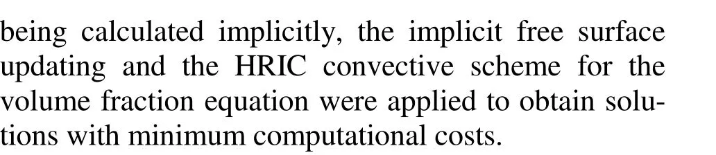
School of Mechanical Engineering, Kyungpook National University, Sangyeok-dong, Buk-gu, Daegu, Korea,
E-mail: Chsohn@knu.ac.kr
Numerical analysis of vortex core phenomenon during draining from cylinder tank for various initial swirling speeds and various tank and drain port sizes*
SOHN Chang Hyun, SON Jong Hyeon, PARK Il Seouk
School of Mechanical Engineering, Kyungpook National University, Sangyeok-dong, Buk-gu, Daegu, Korea,
E-mail: Chsohn@knu.ac.kr
(Received May 1, 2012, Revised July 26, 2012)
A dimple appears on a free surface while rotating a cylinder tank filled with liquid. The dimple starts to concentrically deeper to a drain port at the bottom center of the tank. Over time, the dimple penetrates the drain port, a free surface forms a long and slender string shape in the tank, and a so-called vortexing (air core) phenomenon occurs. The generation of a vortex core depends on the size of the tank and drain port, and on the properties of the liquid in the tank. In this study, the liquid level and the time at which the vortex core is initially generated are numerically investigated using different values of tank diameter, drain port diameter, and initial tank rotational speeds. Instead of a full three-dimensional analysis, a two-dimensional axisymmetric simulation is conducted. The momentum conservation equation in the circumferential direction is additionally solved in the two-dimensional mesh system. Several non-dimensional variables are created: the ratio of the air core generation distance and tank diameter, the diameter ratio of the tank and drain port, the rotational Reynolds number, the rotational Froude number, and the rotational Weber number. Finally, the nondimensional air core generation distance is correlated with the other non-dimensional parameters.
air core, vortex core, dip penetration, vortexing, draining
Introduction
All the aforementioned studies considered draining with no swirling motion. If swirling motion is added by rotating the cylinder or stirring the inside liquid, the dip progression is accelerated and the air core is generated much earlier. Despite considerable research efforts in the hydraulic engineering field to elucidate the air core vortexing phenomenon, a full understanding still requires improved theories and experimental bases. Odgaard[4]developed an equationcorrelating some dimensionless variables to predict the critical height. Their research was based on the Rankine vortex model. This model uses assumed velocity profiles: the linear radial velocity profile, the corresponding axial velocity profile to satisfy the continuity condition, and the circumferential velocity profile expressed as a function of radial position. The main idea involves a balance of forces acting on the free surface (e.g., the pressure and the surface tension force). From this force balancing procedure, they tracked the time evolution of the free surface.
Many experimental studies have been conducted in order to validate the various mathematical models. Ramamurthi et al.[5]tried to see the flow structure inside a tank. They devised a flow visualization facility composed of nets and tufts, and observed the flow pattern inside the tank based on the deflection of the nets. They characterized the effect of the drain port size on air core generation by analyzing the flow structure inside the tank.
Efforts to understand the related physics and develop a simple mathematical model are ongoing. Recently, Tran et al.[6]developed a one-dimensional analytic model applicable to the wide range of the Froude number for the phenomenon. To track the free surface evolution they used the depth-averaged flow method, which is commonly used to simulate open channel flow. They compared their prediction for the critical height with experimental results. Li et al.[7]experimentally and analytically studied vortex generation for the case of a liquid that is forcibly sucked by a pump. They used the Particle Image Velocimetry (PIV) flow visualization method and the standard turbulence model in their flow simulation. The classical Rankine vortex model was used to update the boundary conditions for the momentum and pressure on the free surface of the vortex core.
Vortexing causes air entrainment and harms mechanical facilities. In addition, dip penetration makes the drain time longer by narrowing the discharging area. Therefore, methods to prevent or delay air core generation have been studied by many researchers. Gowda et al.[8]used a dish-type suppressor to prevent vortex flow. They reported that the vortex core was not generated if the dish curvature was larger than a specific value. The same group also experimented on a vane-type suppressor[9]. They examined how the vanes function to prevent air core generation using a PIV test. They showed that the vanes push the liquid upward, similar to a pump, and concluded that this could suppress the formation of a vortex core. Experiments have been performed in which the drain port is placed eccentrically[10]. Echávez et al[11]divided drain flow into an axial-direction flow and a radial- direction flow using a specially configured drain port. By regulating the flow rate in each direction, they showed that the formation and progression of dip penetration could be controlled.
Due to improvements in computing power and numerical methods used in simulations, Park et al.[12]were able to realistically simulate the air core phenomenon in draining. They used the Computational Fluid Dynamics (CFD) and the Volume Of Fluid (VOF) free surface tracking method. They numerically characterized the free surface evolution and vortex interaction processes in a tank. Their results showed that generation of a vortex core is strongly related to both the draining itself and the Ekman suction.
The air core phenomenon has been studied experimentally, numerically, and analytically by many prominent research groups. However, we need to continuously improve our physical understanding and develop empowered numerical and experimental capabilities that are beneficial to site engineers. In this study, we fully numerically simulate the vortex core phenomenon in a cylinder tank during draining, and compare internal flow structures such as velocity vectors and streamlines on cross-sectional planes, with and without generated air cores. The physical cause of the air core phenomenon is explained in detail based on our numerical observations for various cases. We vary the tank and drain port diameters and the tank rotational speed to establish the criterion for air core generation. The influence of each factor is investigated through a parametric study of these factors. The time (the critical time) that the dip fully penetrates the liquid and the level difference (the air core generation distance or the critical distance) between the initial state and the critical state are measured numerically for various cases. Several non-dimensional parameters such as the diameter ratio for the tank and the drain port, the Reynolds number, the Froude number, the Weber number, and the non-dimensional air core generation distance are suggested from the dimensional analysis. A correlation for the dimensionless parameters is developed to characterize vortex core generation for different cases.
1. Numerical analysis
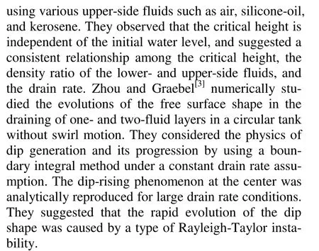
A schematic of the system used in our study is shown in Fig.1. The reference cylinder tank has a 90 mm inside diameter and a 450 mm height. The reference diameter of the drain port is 6 mm and its height is 15 mm. The tank was initially filled with water to a level of 350 mm from the bottom of the tank. The top of the tank was opened so that the liquid water was in contact with the ambient air at 1 atm. For the reference case, 390 nodes were used in the axial direction, 290 nodes were used for the liquid side and the others for the air side at the initial state. A total of 45 nodes were assigned in the radial direction, 5 nodes were used for the drain port region. Ten nodes were used along the length of the drain port. The number ofnodes used in the simulations varied case-by-case according to the dimensions. However, the intervals between the neighboring nodes were usually kept within 1 mm to 2 mm in all cases. The test results for grid dependency are described in Section 2 (Results and discussions). The adopted mesh system showed negligible grid dependency and good agreement with the experimental results.
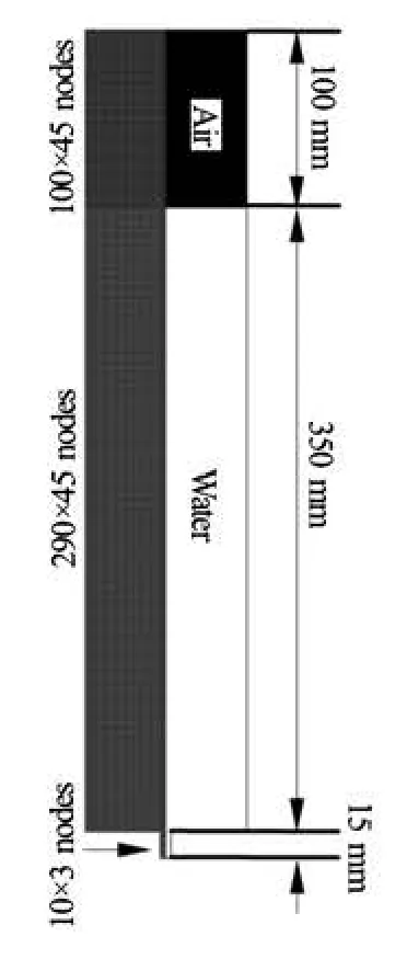
Fig.1 Schematic and basic grid system for reference test case
Table 1 Test ranges of each parameter
The operational and geometrical parameters investigated in this study are the tank diameter, the drain port diameter, and the initial swirl speed of the tank. The testing ranges of each parameter are summarized in Table 1. Two tank diameters, 90 mm and 120 mm, were tested. The drain port diameter was varied from 6 mm to 24 mm, and a total of four cases of drain port diameter were simulated. Seven tank rotating speeds varying from 40 rpm to 180 rpm (revolution per minute) were used. A total of 56 cases were simulated in this study.
Many researchers have been concerned with how the swirl speed affects the generation of an air core because it was empirically revealed that the swirl motion accelerates air core generation. In fact, the swirl intensity affects how early or fast the air core is generated. Therefore we need to observe how the swirl motion contributes to the generation of the air core. In this study, we observed this phenomenon while changing the tank diameter and the drain port diameter.
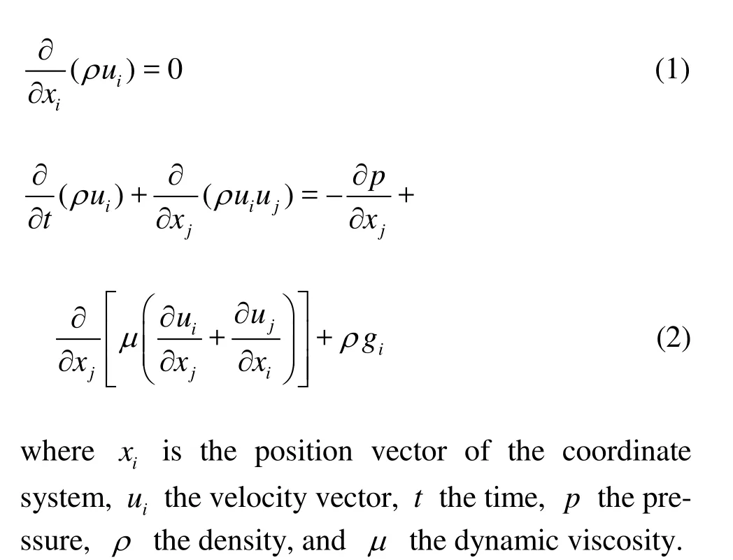
To describe the swirling and draining flow in a tank, an axisymmetric equation set for the conservation of mass and momentum was selected. Although the actual draining process accompanies a spiral motion on the free surface, the flow field is assumed to be an axisymmetric swirling flow to avoid the complexity of solving a three-dimensional problem. The axisymmetric assumption is satisfactory for the capture of the air core phenomenon, as demonstrated by the numerical analysis results described in Ref.[12].
For transient, incompressible, laminar, and freesurface flows under an axisymmetric assumption, the following conservation equations for mass and momentum were selected as the set of governing equations:
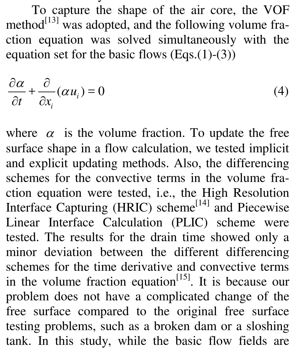
The whole simulation process is divided into the following three steps. First, the tank side wall rotates for 10 s with a constant angular velocity, starting from a stationary status. Second, the wall rotation stops, and the liquid in the tank freely rotates due to inertia for 3 s without draining. Finally, draining is initiated by opening the drain port. The processes are listed in Table 2. The second process was inserted for the short time interval to manipulate the motor and valve in the experiment[12].
Table 2 Event scenario for drain simulation
In the initial rotating process, the fluid in the tank rotates like a rigid body. During the wall-stop and draining processes, the rotational motion in the tank slowly decays. Thus, the only flow-driving force is gravity. The turbulent disturbance in the tank is nearly zero, even if it exists, it rapidly dissipates during draining. In order to determine if the flow regime is laminar or turbulent, we simulated the flow under both thelaminar and turbulent assumptions. The resulting drain-time data shows a large difference between the laminar and turbulent cases. The laminar simulation results showed much better agreement with experiments than the turbulent simulation results.
The flow pattern can be assumed to have no circumferential gradient with respect to the flow variables. However, the flow has a circumferential component of velocity, which has a spatial distribution in the tank and slowly decays with time. To find the swirl velocity component in a two-dimensional mesh system, the following conservation equation for tangential momentum was applied in addition to the basic axisymmetric governing equation set (Eqs.(1) and (2))
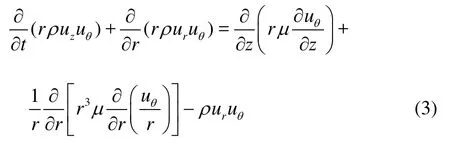
where z is the axial component of the coordinate system,r the radial coordinate component,urthe radial velocity component, and uθthe tangential velocity component. Equation (3) was obtained by eliminating all circumferential gradient terms in the circumferential momentum conservation equation in a cylindrical coordinate system. This is very useful and practical in terms of the computational cost because the high level flow information, including all three velocity components can be obtained on just a two-dimensional mesh system.
To solve all flow variables and the shape of the free surface, we used the Finite Volume Method (FVM)-based commercial CFD code, Fluent 6.3. A constant pressure boundary condition of 1 atm was applied at the top of the tank and the drain port exit. All walls were assumed to be viscous no-slip walls. The surface tension coefficient between water and air was kept constant at 0.0712 N/m and a gravitational acceleration of 9.81 m/s2was applied. The time step size was set to seconds. Computers with the Intel Xeon processors with eight nodes were used. The computation required about 72 h of CPU time to obtain a solution for 900 000 time steps.
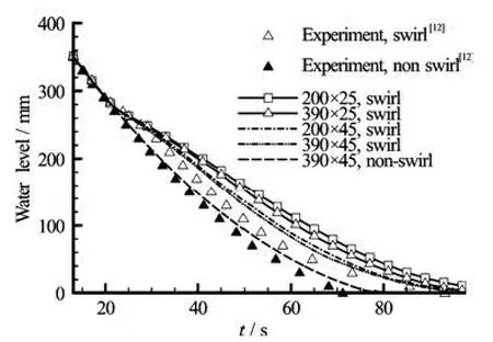
Fig.2 Comparison of water level descents for various grid systems with experiment (D =90 mm,d =6 mm and =ω120 rpm)
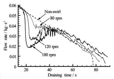
Fig.3 Drain flow rate changes for cases of various tank rotation speeds and the non-swirl case (D =90 mm,d =6 mm)
2. Results and discussions
2.1 Comparison of drain time
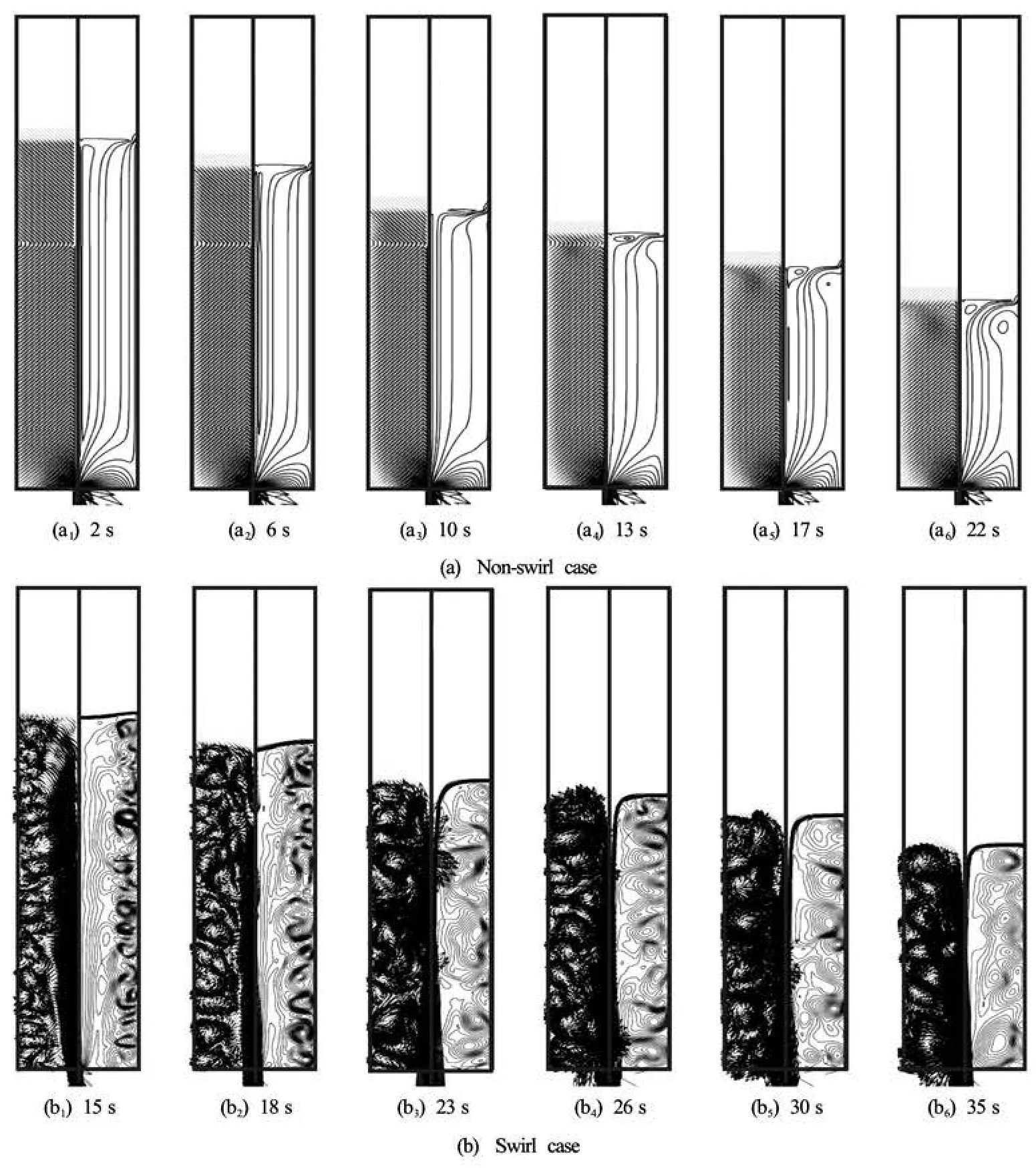
Fig.4 Progression of velocity vector and streamline in tank during draining (D =90 mm,d =6 mm and ω=120 rpm)
In Fig.2 the descents of the water levels on the side wall versus time are compared with the results of the experiment described in Ref.[12]. For the grid dependency check, the results for various grid systems are depicted together. The tank diameter is 90 mm, the drain port diameter is 6 mm and the tank rotational speed is 120 rpm. The results show that the descending speeds of the water level are similar for all cases in the early stage of draining. However, the descending speed slowly changes at 20 s because the air core develops and the drain flow rate decreases. All grid systems tested in this study are in good agreement with this descending speed change. The drain history of the non-swirl-drain case is also depicted in the figure. The results by the experiment and the numerical simulation show a good agreement for the descents of water levels in the non-swirl case too.
A grid systems with 25 and 45 nodes in the radial direction and 200 and 390 nodes in the axial direction were tested. As is shown in Fig.2, increasing the number of nodes in the radial direction is more efficient for producing a realistic solution than increasing the number of nodes in the axial direction. The biggest difference in the drain time between the experiment and numerical simulation results occurs in the coarsest grid system (200×25). Although all the grid systems were sufficient to analyze the phenomenon for the objective of this study, the finest grid system of 390×45 was used for our reference case. This level of grid system was also adopted for all other cases of geometry.
2.2 Mass flow rate
For the non-swirl and three swirling cases, the draining flow rates versus time are compared in Fig.3. All cases show a similar decreasing pattern for the drain flow rate in the early stage of draining (before 20 s), at which point the air core starts to develop. For the non-swirl case, the drain flow rate linearly decreases over the entire draining period due to the lowered water level. After 75 s, the mass flow rate suddenlydecreases due to the generation of the air core or the relatively increased surface tension effect due to the shallow water level.
On the other hand, the swirl cases show an abrupt decrease in the drain flow rate after 20 s as a result of the early generation of the air core. However, the drain flow rates increase again immediately and nearly recover to the non-swirl-case level at about 40 s. The rapid decreases of the drain flow rate are caused by the narrowed effective discharging area due to the generation of the vortex core. The recovery of the drain flow rate during the period from 25 s to 40 s is considered as follows. The drain flow rate is first decreased due to the abrupt generation of the air core, and as a result, the liquid in the tank is pushed to the side wall. However, the pushed liquid immediately undergoes a strong vortexing flow with a circumferential axis (i.e., a Taylor vortex). In the next instant, this strong Taylor vortex near the bottom wall entrains liquid into the drain port. This makes the air core extremely thin at the bottom center, and thus the drain flow rate recovers after 25 s. The drain flow rate decreases again as the water level descends. The decreasing rates are nearly equal to that of the non-swirl case. In the swirl cases, the times for full draining are 5% to 35% longer than that of the non-swirl case.
2.3 Velocity vector and streamline
Figure 4 shows the internal flow structures and the time evolution of the velocity vectors and streamlines. The velocity vector is displayed in the meridian planes, thus, the swirl components are excluded. The air zone is not displayed to better show the flow structures in the liquid region. The vector plots at every moment are displayed using the same length scale so as to see each of the internal flow structures comparatively.
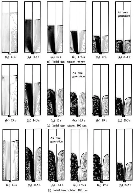
Fig.6 Progression of velocity vector and streamline in a tank during draining for various tank rotational speeds (D =120 mm,d = 1 8 m m )
In the non-swirl case shown in Fig.4(a), the nearly uniform velocity distribution was maintained throughout the whole liquid zone even if the liquid level decreased over time. The streamlines are parallel to the tank axis in almost all the liquid zones. And all streamlines gather to the drain port finally. The liquid stacked in the tank is sequentially drained. There are no flow-driving forces except gravity, therefore, the large radial and axial velocities near the drain port are entirely due to the sudden contraction of the flow passage. However, no significant velocity magnitude is observed on the free surface. According to the kinematic condition on a free surface, a particle on a free surface should remain in its position on the free surface permanently. Thus, the non-swirl case had no dimple on the free surface, and the free surface is flat during most of the draining period. As such, the draining process itself does not influence the formation of the dimple or air core until the liquid level became very low.
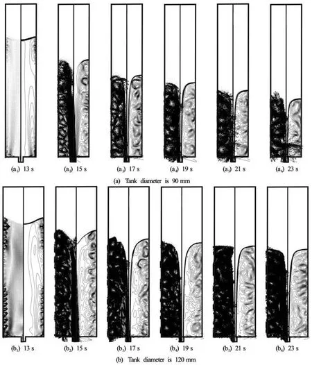
Fig.7 Progression of velocity vector and streamline in a tank during draining (D =12 mm,ω=180 rpm)
While the side wall rotated prior to draining, the flow inside the tank looked like a kind of rigid body rotation, that is, the only existing velocity component is the circumferential component proportional to the radial position. After stopping the side-wall rotation, some flow structures slowly develop on the meridian plane as shown in Fig.4(b). The Taylor vortex circulating in a circumferential axis appears near the side wall. As is shown in the streamline distribution, the small vortex cells start to be generated near the side wall in the early stage of draining. As the draining continues, the vortices remain in succession until the end of the draining, and expand their sizes by combining with one another.
The Taylor vortex forms a kind of 3-D torus loop. If this torus loop expands its volume in the tank, most of the liquid is confined in the tank, and the region contributing to the draining due to downward axial flow becomes small and is concentrated toward the center. Therefore, the center of the free surface is tugged down to the drain port. As a result, the air core is generated in the tank center.
Meanwhile, strong swirling motion occurred near the drain port after the draining starts. The time evolution of the circumferential velocity is represented in Fig.5. The liquid near the side wall at the bottom first moves to the drain port due to the draining. The moved liquid particles accelerate the angular velocity to conserve angular momentum. Once the air core is generated, the liquid at the bottom is confined by the aforementioned Taylor vortex, and the liquid on the free surface starts to drain. In this status, the liquid transports its angular momentum more effectively because it is exposes to the free boundary and not to the viscous wall. Therefore, the spiral vortexing flow of the air core is completed.
2.4 Parametric study
2.4.1 Initial Swirl speed
Figure 6 shows the time progression of the internal flow structures for three different initial swirl speeds. To exclude the effects of other parameters such as the tank diameter and the drain-port diameter,the tank diameter was kept at 120 mm and the drainport diameter at 18 mm. The results for the initial swirl speeds of 40 rpm, 100 rpm and 180 rpm are compared together.
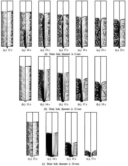
Fig.8 Progression of velocity vector and streamline in a tank during draining for various drain port diameters (D =90 mm,ω= 120 rpm)
As the swirl speed increases, the Taylor vortex on the side wall would be generated earlier. The flow pattern before the Taylor vortex formed is similar to that in the case of the non-swirl draining shown in Fig.4(a), with a well-stratified drain and streamlines parallel to the axis. By comparing these figures, we confirm that the air core generation is strongly related to the growth of the Taylor vortex. As was previously mentioned, the torus-shaped vortex keeps the large parts of the liquid inside the tank and concentrates the draining liquid into the center region.
2.4.2 Tank diameter
To determine the effect of the tank diameter, the two different tank diameters (90 mm and 120 mm) were used. For the two cases, the tank’s rotational speed and the drain-port diameter were fixed at 180 rpm and 12 mm, respectively. Figure 7 compares the time progressions of the internal flow fields. For the two cases, the air core was generated at a similar time, around 15 s. However, the liquid levels when the air core was generated for the first time were slightlydifferent. Basically, the drain flow rate dominantly depends on the liquid level. The absolute quantities of drained liquid for the two cases are similar during the same time interval for a similar water level. Therefore, the larger tank shows a smaller declining rate of the liquid level because it contains more liquid in the tank. Consequently, the air core is generated at a relatively higher level for the case of the larger tank diameter.
More vigorous secondary flows were observed in the larger tank. We also believe that the intensity of the Taylor vortex is related to the circumferential component of the linear velocity, not the angular velocity, because the two cases have the same angular velocity of 180 rpm. In spite of these different Taylor vortex intensities, the two cases generate the air core at a similar time. This suggests that the air core generation is intimately connected with not only the intensity of the Taylor vortex but also something (it may be the spatial expansion of the Taylor vortex).
2.4.3 Drain-port diameter
To check the effect of the drain-port diameter, four different drain-port diameters (6 mm, 12 mm, 18 mm and 24 mm) were tested. To simplify the figure, only the cases of 6 mm, 12 mm and 24 mm are presented in Fig.8. The tank diameter and the tank rotation speed were fixed at 90 mm and 120 rpm, respectively. As was expected, the drain-port diameter greatly affects the drain flow rate.
The bigger drain-port induces greater axial flow and a faster decrease in the liquid level. In the large drain-port diameter case shown in the figure, the strong axial flow appears to interfere with the growth of the Taylor vortex in the radial direction. This shows again that the radial expansion of the Taylor vortex is important to our understanding of the air core.
2.4.4 Correlation equation
The parametric simulation results are summarized in Figs.9-11. Figure 9 shows the critical time tcwhen the air core appears for the first time. Figure 10 shows the air core generation distance Lc.Lcis the water level difference between the initial state and the critical stateHi-Hc, where Hcis the initial water level and Hcis the critical height (the water level at the critical time). The critical distance divided by the critical time results in the critical speed for air core generation. These results are shown in Fig.11.
As is shown in Fig.9, the critical time non-linearly decreases with the rotation speed, i.e., the air core is generated much later as the initial rotation speed decreased. Also, the critical time appears to be independent of the tank diameter. The air core generation time is irrelevant to the tank size, which means the air core generation is connected with only the internal flow characteristics inside the tank and is not related to the tank size. As the drain-port diameter increases, the critical time decreases and converges to the specific value, as shown in Fig.9(b). The enlarged drain port promotes the axial flow inside the tank, and the changed inner flow pattern affects the air core generation time.
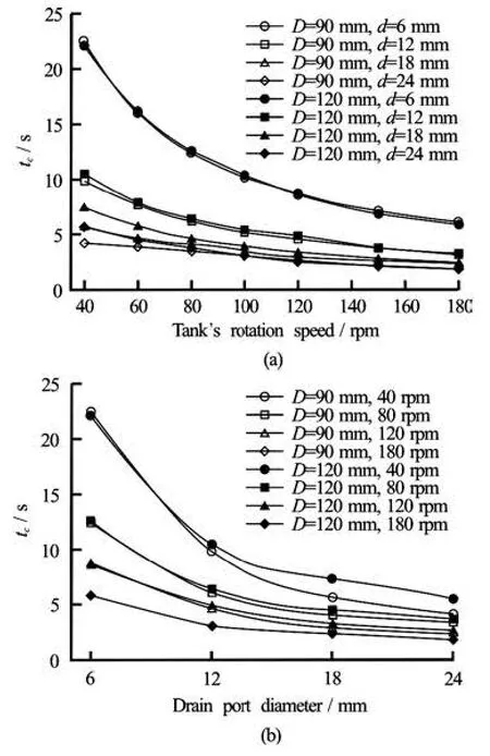
Fig.9 Critical times for various simulation cases
The decreasing pattern of the critical distance for the rotational speed is similar to that of the critical time as shown in Figs.9(a) and 10(a). However, from the results, we note that the critical distance is also affected by the tank diameter. On the other hand, the critical time appears to be unaffected by the tank diameter. This is natural because the water level is highly related to both the drain flow rate and the contained water amount in the tank.
The air core phenomenon is affected by the tank rotation speed, the drain port size and the tank size. However, its generation time shows no dependency on tank size. These observations about the critical distance and the critical time make us to think that the air core phenomenon is related to something transported or developed inside the tank. Therefore, we considered the speed of the air core generation. In Fig.11, the air core generation speeds (the critical speeds) are shown for every case. In particular, the critical speed appears to be irrelevant to the tank rotational speed. That is, the effect of the shortened critical time due to increasing the rotation speed (as shown in Fig.8) is fully compensated by the shortened critical distance shown in Fig.10. However, the effect of the drain portsize and the tank size still remain as shown in Fig.11(b). The smaller tank (D=90 mm) shows the larger critical speed. The critical speed increases exponentially as the drain port diameter increases.
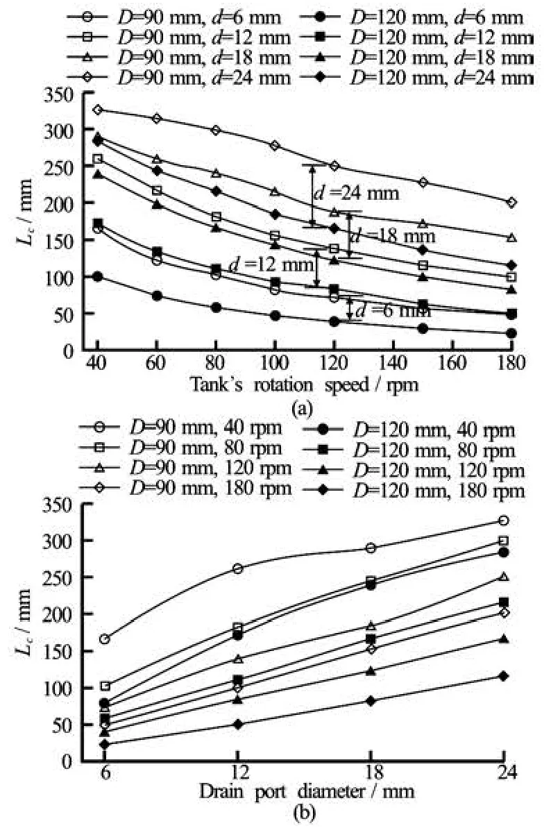
Fig.10 Critical heights for various simulation cases
A slightly different pattern for the critical speed for the case of D =90 mm and d=24 mm is shown in Fig.11(a). This case has the smallestD/ d=3.75, and is expected to be affected in a different way by the inertia forces due to tank rotation (swirling momentum) and draining (axial momentum by gravity). The tank rotation tends to retard the draining speed and extend the draining time, as shown in Fig.3. On the other hand, axial momentum due to the gravity force boosts the draining speed. As D/ddecreases, the effect of the axial momentum becomes more dominant than that of the swirling momentum because of the increased drain flow rate. Thus, in the case ofD=90 mm andd=24 mm, the jump of the critical speed near 100 rpm could be analyzed with respect to the change in the dominant working inertia force. The behavior of the dominant force over a wide range of rotational speeds and the geometry are issues that need to be considered separately in future work.
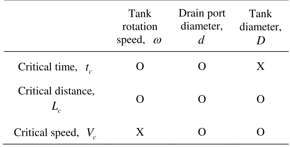
Table 3 Relevance of each parameter to the critical time, distance, and speed
The relevance of each testing parameter (the tank rotation speed, the tank diameter, and the drain port diameter) to the indices describing the air core phenomenon (the critical time, the critical distance, and the critical speed), is summarized in Table 3. From the results we selected the critical distance as the representative index describing the air core phenomenon.
The related flow variables are the tank rotational speed ω, the tank diameterD, the drain-port diameterd , the liquid properties (densityρ, dynamic viscosityμ, and surface tension coefficientσ), and the gravitational accelerationg. These variables were used to conduct the dimensional analysis. The five non-dimensional parameters related to the phenomenon were obtained using the Buckingham Pi theorem.
These non-dimensional parameters are the dimensionless critical distanceL?=(Hi-Hc)/D, the diameter ratio of tank to the drain portD?=D/d, the rotational Reynolds numberRe =ρD2ω/μ, the rotational Froude numberFr=D2ω/g, and the rotational Weber numberWe=ρD3ω2/σ. With the numerical results, we obtain the following correlationamong the non-dimensional parameters.
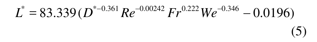
A comparison of the numerical results with the correlation equation is shown in Fig.12.
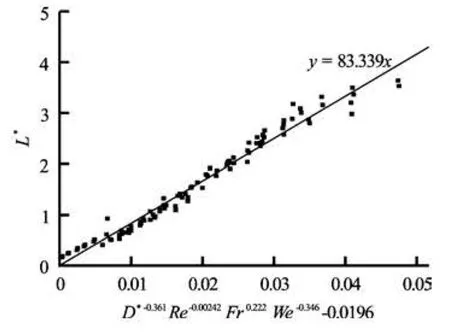
Fig.12 Comparison of present simulation results with correlation equation
3. Conclusion
We have studied the air core phenomenon during the draining process of initially rotating cylinder tanks. The free surface motions and related flow fields, including the velocity vector and the streamline were compared for a variety of tank rotational speeds, tank diameters, and drain-port diameters. It is concluded that the phenomenon is closely related to both the intensity of the Taylor vortex and its spatial expansion. The intensity of the Taylor vortex is proportional to the circumferential component of the linear velocity. However, its spatial growth depends on the reciprocal action with the axial momentum. From these phenomenological observations based on our numerical results, we have created five non-dimensional parameters relating the phenomenon: the non-dimensional critical distance, the tank to drain port diameter ratio, the rotational Reynolds number, the rotational Froude number, and the rotational Weber number. Finally, a correlation among the non-dimensional parameters has been developed.
Acknowledgements
This work was supported by the Basic Science Research Program through the National Research Foundation of Korea (NRF) funded by the Ministry of Education, Science and Technology (Grant No. 2010-0024619).
[1] CHOI J. W., CHOI Y. D. and , LIM W. S. et al. Numerical analysis on the flow uniformity in a pump sump model with multi pump intake[J]. Journal of Fluid Machinery, 2009, 12(4): 14-22.
[2] LUBIN B. T., SPRINGER G. S. The formation of a dip on the surface of a liquid draining from a tank[J]. Journal of Fluid Mechanics, 1967, 29: 385-390.
[3] ZHOU Q. N., GRAEBEL W. P. Axisymmetric draining of cylindrical tank with a free surface[J]. Journal of Fluid Mechanics, 1990, 221: 511-532.
[4] JACOB ODGAARD A. Free-surface air core vortex[J]. Journal of Hydraulic Engineering, ASCE, 1986, 112(7): 610-620.
[5] RAMAMURTHI K., THARAKAN T. J. Flow visualisation experiments on free draining of a rotating column of liquid using nets and tufts[J]. Experiments in Fluids, 1996, 21(2): 139-142.
[6] ANH T. N., HOSODA T. Free surface profile analysis of flows with air-core vortex[J]. Journal of Applied Mechanics, 2004, 7(2): 1061-1068.
[7] LI Hai-feng, CHEN Hong-xun and MA Zheng et al. Experimental and numerical investigation of free surface vortex[J]. Journal of Hydrodynamics, 2008, 20(4): 485-491.
[8] GOWDA B. H. L., JOSHY P. J. and SWARNAMANI S. Device to suppress vortexing during draining from cylindrical tanks[J]. Journal of Spacecraft and Rockets, 1996, 33(4): 598-600.
[9] SOHN C. H., JU M. G. and GOWDA B. H. L. Draining from cylindrical tanks with vane-type Suppressors – A PIV study[J]. Journal of Visualization, 2009, 12(4): 347-360.
[10] SOHN C. H., GOWDA B. H. L. and JU M. G. Eccentric drain port to prevent vortexing during draining from cylindrical tanks[J]. Journal of Spacecraft and Rockets, 2008, 45(3): 638-640.
[11] ECHáVEZ G., MCCANN E. An experimental study on the free surface vertical vortex[J]. Experiments in Fluids, 2002, 33(3): 414-421.
[12] PARK I. S., SOHN C. H. Experimental and numerical study on air cores for cylindrical tank draining[J]. International Communications in Heat and Mass Transfer, 2011, 38(8): 1044-1049.
[13] HIRT C. W., NICHOLS B. D. Volume of fluid (VOF) method for the dynamics of free boundaries[J]. Journal of Computational Physics, 1981, 39: 201-225.
[14] FLUENT INC. Fluent 6.3 Users guide[M]. Fluent Inc., 2006.
[15] PARK I. S., SON J. H. and SOHN C. H. Numerical study for characteristics of internal flow including an air core in a cylindrical tank[J]. Transactions of the Korean Society of Mechanical Engineers B, 2012, 36(3): 269-276.
Nomenclature
D– Tank diameter
D?– Diameter ratio of tank to drain port
d – Drain port diameter
Fr – Rotational Froude number
gi– Gravity vector
Hc– Critical height
Hi– Liquid level at initial state
Lc– Critical distance (air core generation distance)
L?– Dimensionless critical distance
p– Pressure
r – Radial component of coordinate system Re – Rotational Reynolds number
t – Time
tc– Critical time
ui– Velocity vector
Vc– Critical speed (Lc/tc)
We – Weber number
xi– Position vector of coordinate system
z – Axial component of coordinate system
Greek symbols
α– Volume fraction function
μ– Dynamic viscosity
ρ– Density
σ– Surface tension
ω– Angular velocity of tank
Subscripts
θ– Circumferential direction
r – Radial direction
z – Axial direction
10.1016/S1001-6058(13)60353-4
* Biography: SOHN Chang Hyun (1961-), Male, Ph. D., Professor
PARK Il Seouk,
E-mail: Einstein@knu.ac.kr
 水動(dòng)力學(xué)研究與進(jìn)展 B輯2013年2期
- 水動(dòng)力學(xué)研究與進(jìn)展 B輯的其它文章
- An experimental study on runup of two solitary waves on plane beaches*
- Electro-osmotic flow of a second-grade fluid in a porous microchannel subject to an AC electric field*
- Parametric instability of a liquid metal sessile drop under the action of low-frequency alternating magnetic fields*
- Influence of flow field on stability of throttled surge tanks with standpipe*
- Influence of emergent macrophyte (Phragmites australis) density on water turbulence and erosion of organic-rich sediment*
- Hydrodynamic performance of a vertical-axis tidal-current turbine with different preset angles of attack*