
Discharge and jet characteristics of gliding arc plasma igniter driven by pressure difference
2022-11-17 02:59:42XinyaoCHENG程信堯HuiminSONG宋慧敏ShengfangHUANG黃勝方YifeiZHU朱益飛ZhiboZHANG張志波ZhenyangLI李振陽(yáng)andMinJIA賈敏
Plasma Science and Technology 2022年11期
Xinyao CHENG(程信堯),Huimin SONG(宋慧敏),*,Shengfang HUANG(黃勝方),Yifei ZHU(朱益飛),Zhibo ZHANG(張志波),Zhenyang LI(李振陽(yáng)) and Min JIA(賈敏)
1 Science and Technology on Plasma Dynamics Laboratory,Air Force Engineering University,Xi’an 710038,People’s Republic of China
2 China Aerodynamics Research and Development Center,Mianyang 621000,People’s Republic of China
3 Institute of Aeroengine,Xi’an Jiaotong University,Xi’an 710049,People’s Republic of China
Abstract Stable combustion in an afterburner can help increase the thrust of the engine in a short time,thereby improving the maneuverability of a fighter.To improve the ignition performance of an afterburner,a twin-duct ignition platform was designed to study the performance of a gliding arc plasma igniter in close-to-real afterburner conditions.The research was carried out by a combination of experiments and simulations.The working environment of the igniter was explored through a numerical simulation.The results showed that the airflow ejected from the radiating holes formed a swirling sheath,which increased the anti-interference ability of the airflow jet.The influence of the pressure difference between the inlet and outlet of the igniter(Δp),the flow rate outside the igniter outlet(W2),and the installation angle(α)on the singlecycle discharge energy(E)as well as the maximum arc length(L)were studied through experiments.Three stages were identified:the airflow breakdown stage,the arc evolution stage,and the arc fracture stage.E and L increased by 107.3% and 366.2%,respectively,withΔp increasing from 10 to 70 Torr.The relationship between L andΔp obtained by data fitting is L=3-2.47/(1+(Δp/25)4).The relationship of L at different α is Lα=0°>(Lα=45° and Lα=135°)>Lα=180°>Lα=90°.E and L decrease by 18.2% and 37.3%,respectively,when Δp=45 Torr and W2 is increased from 0 to 250 l min-1.
Keywords:plasma,ignition,gliding arc
1.Introduction
Stable combustion in an afterburner can comprehensively improve the aircraft’s maneuverability and expand the flight envelope,thus enhancing the fighter’s air superiority.However,because of the sizeable swirling degree,low oxygen content,and wide range of airflow velocity and pressure in the afterburner,successful ignition and stable combustion are challenging to realize.Alexander Niet al[1]established a self-excited acoustic model based on the ignition time of an afterburner,which is prone to delay during continuous combustion.Langghorne[2]studied the surge phenomenon in an afterburner and found that the energy of the oscillation originates from the pulsation of the heat release rate caused by the flame response to the pressure pulsation.Macquisten and Dow[3]studied the combustion instability caused by air mixing in a turbofan engine afterburner.The traditional spark ignition method can no longer meet the performance requirements of future engines for afterburners[4];therefore,a novel ignition scheme is required.
The application of plasma ignition in aero engines has attracted the attention of many researchers[5-7].Plasma enhances the ignition and combustion effects through thermal,dynamic,and transport effects[8-11].Brandeet al[12]attempted to influence a flame through an electric field.Haselfootet al[13]used discharge plasma to enhance the ignition process in a low-pressure environment.Since the 1990s,research on the mechanism and application of plasma ignition have attracted considerable attention.Baoet al[14-17]used methane and ethylene airflows as fuels for ignition experiments.Studies have found that the active particles produced by plasma can reduce the minimum ignition energy and shorten the ignition delay time during the chemical reaction process.
The concept of gliding arc discharge was first proposed by Czechowski[18]and Lesueur[19]in 1990.The basic principle of gliding arc discharge is to apply an electric field on one or more electrodes to create arc channels between the electrode gaps.Airflow is continuously blown out from the channel,and the arc slides along the direction of airflow in the electrode gap.The arc periodically undergoes a cyclic process of breakdown,elongation,disappearance,and breaking down again under airflow action,thus forming a sliding arc discharge[18,20].The gliding arc has both lowand high-temperature plasma characteristics[21].On one hand,the high-temperature electrons generated during the discharge process are accelerated to generate more active molecules and promote chemical reactions[22].On the other hand,it has a higher energy utilization rate.Wanget alfound that the gliding arc exhibits typical non-equilibrium characteristics in the process of CO2conversion through calculations.Compared with the thermal process,the gliding arc conversion method has higher conversion efficiency and energy utilization efficiency[23-25].Zhu[26]conducted an optical diagnosis of gliding arc discharge plasma in the air at atmospheric pressure,and calculated that the electron temperature of the gliding arc is 9300-9500 K.Experimental results show that the gliding arc discharge is in a highly nonequilibrium state.Compared with spark ignition,gliding arc discharge ignition has a longer contact and action time with the combustible material which is more conducive to the development of the flame.The electrons near the arc column area of the gliding arc are violently collided by the strong electromagnetic field.The violent collision of the electrons causes the electron temperature to rise rapidly,increases the ambient temperature of the gliding arc and enhances the fuel atomization effect[27].Meanwhile,gliding arc plasma has essential application prospects in ignition and combustion support and has attracted wide attention from scholars[28-30].Ombrelloet al[31,32]analyzed the effect of a segmented non-equilibrium gliding arc in methane-air on flame development.The experiment showed that the combustion effect enhancement was mainly affected by the thermal effect during the low-power discharge in the airflow.Heet al[33]studied the influence of a rotating gliding arc on the combustion efficiency and flame extinguishment of a swirling combustor.Zhonget al[34]analyzed a blade-type alternating current(AC)gliding arc discharge process.The results show that the average discharge power of the gliding arc first increased linearly and then remained stable with increasing airflow.Gaoet al[35]used planar laser-induced fluorescence technology to measure the instantaneous structure of a gliding arc and found that long-lived substances produced by the gliding arc discharge increase the flame propagation speed through oxidation.Linet al[36]proposed a multichannel gliding arc system using the principle of multichannel discharge.The results showed that a three-channel gliding arc(3-GA)and a five-channel gliding arc(5-GA)have higher average power than a single-channel arc(1-GA)under a constant wind speed.Jiaet al[37]studied the instantaneous power of a gliding arc in a double-headed swirling combustion chamber and the CH*chemiluminescence imaging of the ignition process.The flameout limit of the single-channel gliding arc was widened,and its lean ignition limit expanded by approximately 67% compared with a traditional spark igniter.Zhanget al[38]found that when a gliding arc was used in an ethylene fuel supersonic combustion chamber withMa=2.92 and a global equivalent ratio of 0.16,the wall pressure was increased by an average of 12% and the timeaveraged flame area by 27%.
In addition,the ignition effect of the gliding arc was significantly affected by the discharge.Heet al[39]analyzed the dynamic process of a plasma jet.The experimental results showed that a high-speed rotating airflow has different degrees of influence on arc development and strong pulsation in the jet formation process.Liuet al[40]studied the influence of different working medium flow rates on a plasma igniter jet.The experimental results showed that the length of the jet in the stable phase first increases and then decreases with an increase in the mass flow of the working medium.Jiaet al[41]experimented on the electrical characteristics of a gliding arc plasma jet igniter,and the results showed that the jet penetration depth has an extreme value.
Relatively few studies have been conducted on enhanced ignition in afterburners.To date,research on gliding arc plasma ignition has mainly focused on the main combustion chamber of a turbine engine and the combustion chamber of a ramjet engine.To achieve a better ignition effect of the gliding arc in an afterburner,it is necessary to understand the discharge and evolution characteristics of a gliding arc igniter.However,no suitable flow field environment for experimental research currently exists and,thus,the progress in gliding arc plasma on strengthening the ignition of an afterburner is decelerating.In this study,a twin-duct ignition platform was designed to simulate an afterburner’s induct and bypass.The discharge characteristics and jet evolution of the gliding arc plasma igniter driven by pressure difference were studied.A numerical simulation was conducted on the flow field to analyze the igniter flow field structure.The effects of changing the pressure difference between the inlet and outlet of the igniter(Δp),the flow rate outside the igniter outlet(W2),and the installation angle(α)on the single-cycle discharge energy(E)and maximum arc length(L)of the gliding arc were studied.
2.Experimental setup
2.1.Gliding arc plasma igniter driven by pressure difference
The structure of the gliding arc plasma igniter driven by pressure difference is shown in figure 1.It is mainly composed of a cylindrical anode with a base,an igniter inner core(cathode),insulating ceramics,and an igniter shell.A gliding arc between the anode head and cathode core is generated by the igniter during operation.Since a large amount of heat is generated during the gliding arc discharge process,causing a local high temperature,the cylindrical anode is processed by a high-temperature alloy.The ignition cable is inserted into the gliding arc igniter,and the cable head is kept in reliable contact with the anode base through an external thread.The ceramic is made of alumina to meet the requirements of insulation and strength.
The working principle of the gliding arc igniter is as follows:outside airflow enters the igniter through a diversion hole,and the airflow inside the igniter is broken down to generate an arc.The arc is continuously rotated and elongated under the action of the airflow,and finally blown out of the cathode channel.The airflow entering the igniter is divided into two parts.(1)The first part flows outward along the shell interlayer,allowing cold airflow to exchange heat with the shell to remove part of the heat generated by the gliding arc discharge,and plays a role in cooling the shell.(2)The second part enters the gap between the inner core and the anode through swirling holes,at which time the airflow has a circumferential velocity.Before entering the cathode channel,the airflow is accelerated in the convergence section and its axial velocity is increased.
The functions of the airflow,which passes through the swirl hole and produces the rotating airflow,are as follows:(1)strengthening the ability of the jetted airflow to resist external interference,(2)ensuring complete heat exchange between the airflow and the anode head,and(3)using aerodynamic forces to ensure the continuous movement of the arc root and weaken continuous ablation of the same position on the anode head due to gliding arc discharge.
2.2.Twin-duct ignition platform
The afterburner is composed of a bypass,induct,center cone,strut stabilizer,and cavity trapped vortex stabilizer,as shown in figure 2.Because the induct and bypass airflows in the afterburner have different sources and do not interfere with each other before the gliding arc igniter,there are two independent airflows with different flow rates entering the afterburner.The diversion hole of the gliding arc igniter is located in the bypass,and the jet outlet of the igniter is located in the induct.The performance of the gliding arc igniter is driven by the pressure difference between the bypass and the induct.
According to the operating mode of the gliding arc igniter in the afterburner and the working conditions that need to be simulated,a twin-duct ignition platform with two independent upper and lower cavities is constructed,as shown in figure 3.The test bench is composed of an inlet section,transition section,experimental section,and exhaust section.The inlet and exhaust sections independently supply and exhaust air.The transition section rectifies the airflow to form a uniform flow field and eliminates the influence of the vortex generated when the airflow passes through the inlet and exhaust sections.To fully rectify,the transition section is designed as an upper and a lower cavity with a length of 300 mm that flows independently.
In the experimental section,the upper and lower cavities withΔpare created by changing the upper cavity flow rateW1and the lower cavity flow rateW2.The upper cavity simulates the bypass,and the lower simulates the induct.The cross-sectional size of the lower cavity is 34 mm×100 mm to ensure that the diversion hole of the gliding arc igniter is located in the upper cavity.The angle between the airflow directions of the upper cavity and the diversion hole is defined as α.The cross-sectional size of the lower cavity is 64 mm×100 mm to ensure that the gliding arc blown out does not touch the lower wall.In the experiment section,a channel that fits the size of the gliding arc igniter is designed.Two quartz observation windows are installed in the lower cavity of the experimental section.The front observation window is 66 mm×165 mm and the bottom observation window is 75 mm×160 mm.The jet length and stiffness of the gliding arc can be observed in the front viewing window.The rotation development of the gliding arc can be seen in the bottom observation window.Pressure sensors are installed at the center of the section of the upper and lower cavities 20 mm away from the outlet to monitor the static pressure in real time.An MKS-690A13TRA is used as a pressure sensor with a range of 0-1000 Torr and a full-scale error of 0.15%.
2.3.Gliding arc characteristic experiment system
The gliding arc characteristic experiment system is composed of an excitation source,an air supply system,a parameter testing system,and a twin-duct ignition platform,as shown in figure 4.
The gliding arc plasma power supply developed in the laboratory is used as the excitation source,adopting high voltage,low current,and low power output.The excitation source is set to a cycle length of 100 ms,a discharge time of 10 ms,and a duty ratio of 10%.In the gliding arc discharge process,ablation of the electrode is severe.The self-made power supply is set to a short duty cycle and low power output mode,which effectively solves the problem of electrode ablation.
The air supply system is composed of an air compressor,dryer,and air tank.A stable airflow in the range of 0-450 l min-1is stably output by the air compressor.The air is supplied in advance and delayed shut-off is adopted to ensure a uniform flow field in the experimental section.
The mirror is placed at an angle of 45°,which can shoot the gliding arc jet and develop the swirling flow with a highspeed camera simultaneously.The high-speed camera
(Phantom V2512)resolution is set to 512×384,the exposure time is set to 10 μs,and the frame rate is set to 25 000 fps.A high-voltage probe(Tektronix P6015A)and a current probe(Tektronix P6021)are used to collect the voltage and current signals.An oscilloscope(Tektronix DPO4104)and the high-speed camera are triggered simultaneously,and the voltage and current waveforms synchronized with the shooting results can be captured.
In the experiment,each working condition is tested three times,and the average of the three sets of experimental results is taken as the final result of the working condition.
3.Numerical simulation of flow field of gliding arc igniter
3.1.Model setup and description
The discharge and shape of the gliding arc are greatly affected by the flow field,so numerical simulation is used to analyze the flow field environment when the igniter is working.Owing to the complicated structure of the igniter,it is impossible to obtain the measurement results for the internal flow field and the outlet flow field of the igniter.Therefore,COMSOL software is used to numerically simulate the flow field area during the arc sliding operation to reveal the flow field structure of the igniter.
According to the size of the lower cavity,the working flow field of the gliding arc igniter and the flow field of the lower cavity of the twin-duct ignition platform are constructed to explore the rules of the airflow ejected from the cathode channel.The model is simplified because not all structures of the gliding arc igniter involve airflow,as shown in figure 5.The front view is translucent to intuitively observe the structure of the computational domain,as shown in figure 5(a).Figure 5(b)shows the top-view structure.
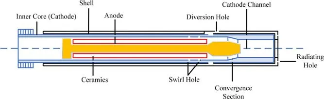
Figure 1.Structure diagram of gliding arc igniter.
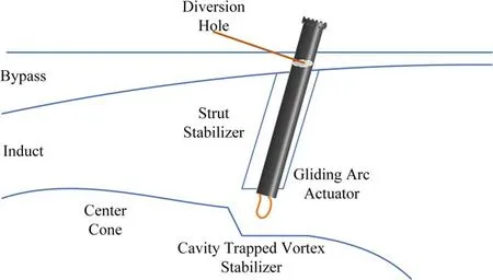
Figure 2.Schematic of afterburner structure.
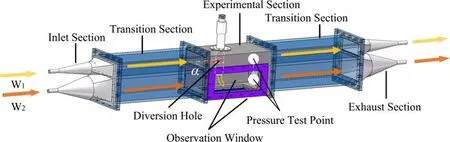
Figure 3.Twin-duct ignition platform.
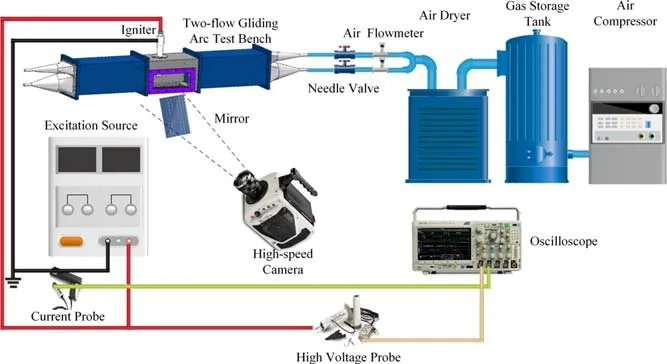
Figure 4.Gliding arc characteristic experiment system.
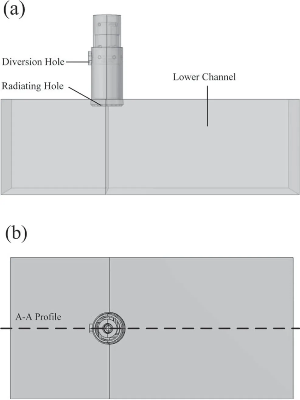
Figure 5.Calculation domain of the gliding arc igniter and the lower cavity of the twin-duct ignition platform.(a)Front view of calculation domain,(b)top view of calculation domain.
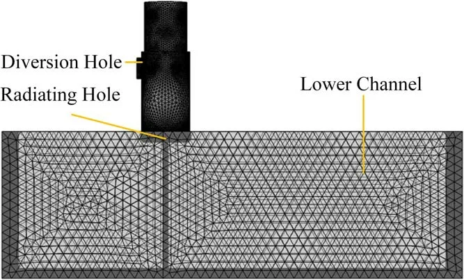
Figure 6.Grid division of the lower cavity of the twin-duct ignition platform and the gliding arc igniter.
The airflow has axial and circumferential velocities as it enters the inner core of the igniter after passing through the diversion and swirl holes.The swirling airflow is accelerated in the convergent section and eventually blown out of the cathode channel.Air is selected as the flow field material,and the parameters that come with the software are selected as the density and dynamic viscosity.The internal flow state of the gliding arc igniter is complex with many separated flows and strong curvature flows,so the turbulent flow model is selected.The inlet of the igniter is set as a pressure boundary condition,and the inlet of the lower cavity is set as a velocity boundary condition.A free tetrahedral mesh in a fluid dynamics method is used for meshing.The number of grid cells is 1.35 million,the tetrahedron is 930 000,and the average quality of the grid is 0.66,as shown in figure 6.
To explore the static pressure of the diversion hole of the igniter at different installation angles,a two-dimensional cylindrical flow model is constructed according to the dimensions of the upper cavity and the igniter shell,as shown in figure 7(a).The laminar flow model is selected in the numerical simulation.The upper cavity inlet is set as the velocity boundary condition,and the upper cavity outlet is set as the pressure boundary condition.The fluid dynamics method is used for meshing,and the free tetrahedral mesh is mainly used,as shown in figure 7(b).
3.2.Analysis of the flow field
Figure 8 shows the velocity cloud diagram of the lower cavity flow field A-A profile withΔp=10 Torr andΔp=45 Torr whenW2=768 l min-1.The numerical results show that an increase inΔpincreases the airflow rate inside the igniter,which is essential for increasingLbecause the aerodynamic force acting on the arc increases.Meanwhile,the airflow blown by radiating holes generates a swirling sheath,which reduces the interference of the airflow from the lower cavity to the airflow blown by the cathode channel.AsΔpincreases,the circumferential velocity of the rotating airflow increases,and the protective effect becomes more apparent.Both the axial and circumferential velocities of the airflow increase,the flow field is more concentrated,and the ability to resist the interference of the lower cavity airflow is more substantial when the airflow is closer to the outlet of the cathode channel.Figure 8 also shows that the deflection angle of the airflow ejected from the cathode channel decreases asΔpincreases.A decrease in the deflection angle of the airflow inevitably leads to a decrease in the offset angle of the gliding arc and an increase in the jet length because the gliding arc is slid and elongated under the driving force of the airflow.

Figure 7.Two-dimensional flow model around a cylinder and meshing.(a)Two-dimensional cylindrical flow model,(b)meshing of a two-dimensional cylindrical flow model.
To explore the influence of the increase in the lower cavity flow rate on the airflow from the igniter,a numerical simulation of the A-A profile velocity cloud diagram withW2=0 l min-1andW2=250 l min-1whenΔp=10 Torr is conducted,as shown in figures 9(a)and(b).The results show that the airflow ejected by the igniter is disturbed by the airflow flow field in the lower cavity and deflected by the aerodynamic force of the airflow flow in this cavity.
Figures 10(a)and(b)show the velocity cloud diagrams of the A-A profile of the lower cavity flow field withW2=768 l min-1andW2=1920 l min-1whenΔp=10 Torr.Figures 9 and 10 show that:(1)The flow field near the exit of the gliding arc igniter is undisturbed under the protection of the swirl sheath.(2)With an increase in airflow and air velocity in the lower cavity,the interference of the airflow from the cathode channel increases.(3)The axial displacement along with the outlet of the cathode channel increases,the protective capacity of the swirl sheath decreases,and the interference of the ejected airflow increases.

Figure 8.Velocity cloud diagram of the flow field at the exit of the gliding arc and the lower cavity withΔp=10 Torr and Δp=45 Torr when W2=768 l min-1.(a)Velocity cloud diagram of the flow field at the exit of the gliding arc and the lower cavity withΔp=10 Torr when W2=768 l min-1,(b)velocity cloud diagram of the flow field at the exit of the gliding arc and the lower cavity withΔp=45 Torr when W2=768 l min-1.
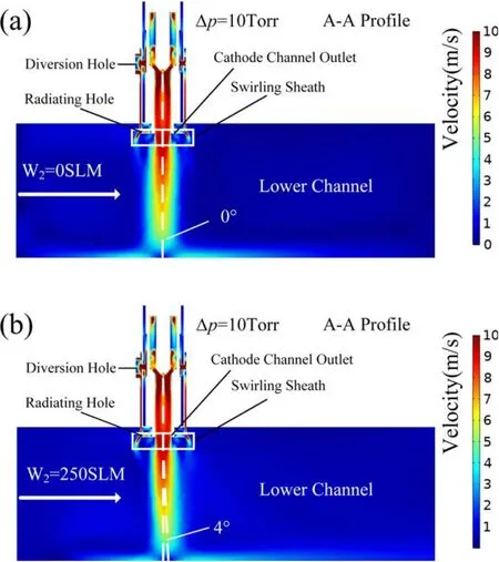
Figure 9.Velocity cloud diagram of gliding arc exit and lower cavity flow field with W2=0 l min-1 and W2=250 l min-1 when Δp=10 Torr.(a)Velocity cloud diagram of gliding arc exit and lower cavity flow field with W2=0 l min-1 whenΔp=10 Torr,(b)velocity cloud diagram of gliding arc exit and lower cavity flow field with W2=250 l min-1 whenΔp=10 Torr.
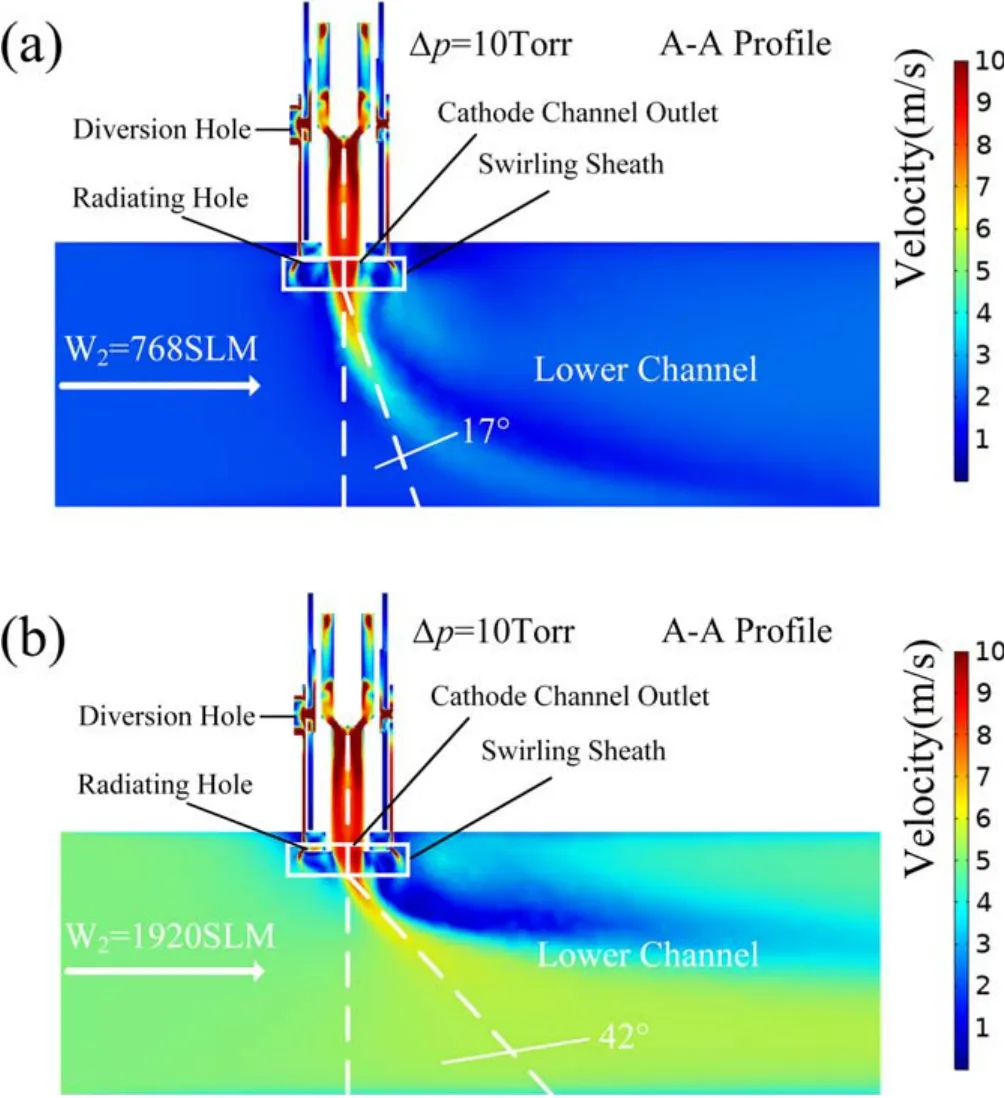
Figure 10.Velocity cloud diagram of gliding arc exit and lower cavity flow field with W2=768 l min-1 and W2=250 l min-1 whenΔp=10 Torr.(a)Velocity cloud diagram of gliding arc exit and lower cavity flow field with W2=768 l min-1 when Δp=10 Torr,(b)velocity cloud diagram of gliding arc exit and lower cavity flow field with W2=250 l min-1 whenΔp=10 Torr.
Figure 11.Numerical simulation results of two-dimensional flow around a cylinder.(a)Static pressure cloud,(b)velocity cloud.
The incoming flow velocity is set to 1 m s-1and the outlet pressure to 760 Torr.Figure 11 shows the change in the static pressure and velocity around the igniter shell when the airflow flows in the upper cavity.The numerical simulation results show that the static pressure relationship around the igniter shell is as follows:Pα=0°>Pα=45°>Pα=90°>Pα=135°>Pα=180°.The relationship between the airflow velocities around the igniter shell isvα=90°>vα=45°>vα=135°>(vα=0°andvα=180°).When α=45° and 135°,the velocities near the igniter shell are approximately the same.The velocity in the upper cavity is low,and the dynamic pressure in the upper cavity can be ignored.
4.Experimental results and discussion
4.1.Evolution process and discharge waveform of gliding arc discharge
Figures 12 and 13 show the voltage and current waveform diagrams and the evolution process diagram of the gliding arc jet when the gliding arc igniter discharges,that is,whenW2=0 l min-1,α=0°,andΔp=45 Torr.The discharge waveforms marked in figure 12(a)are shown in figures 12(b)-(d).The evolution of the jet is shown in the upper part of figure 13,and the development of the swirl is shown in the lower part of the figure.Figure 13 is highlighted with the important stages mentioned in this paper.The phases in which the cycle occurs are only noted for the first time.Att0=0 ms,the airflow inside the igniter is broken down to form a discharge channel.The timet1=1.23 ms indicates that the gliding arc is blown out of the cathode channel and enters the first jet evolution stage,t2=2.32 ms indicates the end of the first jet evolution phase and the beginning of the second jet evolution phase,…andt8=8.64 ms indicates the end of the seventh jet evolution phase and the beginning of the eighth jet evolution phase.t9=9.24 ms indicates the end of the gliding arc discharge cycle.
The gliding arc plasma discharge process can be classified into three stages:the airflow breakdown stage,the arc evolution stage,and the arc fracture stage.
The first stage is the airflow breakdown stage.The voltage and current waveform diagrams show the voltage on the igniter at(t0-0.08)ms,but the current is 0 A,indicating that the air gap is not broken down at this time.The gliding arc igniter is regarded as a capacitor storing energy at(t0-0.08)~t0ms,the charge between the anode and cathode of the gliding arc igniter is continuously accumulated,and the potential difference is increased.Att0=0 ms,the potential difference between the anode and cathode reaches the voltage required for air breakdown,and the air gap is broken down to form an arc.Figure 12(a)shows that the discharge current increases sharply att0,and figure 13 shows that a bright spot appears at the anode of the igniter att0.At this time,a discharge channel is formed.

Figure 12.Voltage-current waveform and discharge images of gliding arc discharges when W2=0 l min-1,α=0°,andΔp=45 Torr.(a)Discharge waveforms of gliding arc igniter in a single cycle,(b)B-G mode,(c)B-GII mode,(d)A-G mode.
Figure 13.Evolution process of the gliding arc captured by a high-speed camera.

Figure 14.Influence ofΔp on E and L.
The second stage is the arc evolution stage.There are three modes in the gliding arc evolution stage:breakdown gliding mode(B-G),transition mode(B-GII),and steady arc gliding mode(A-G).
4.1.1.Breakdown gliding mode(B-G).After the airflow enters the gliding arc igniter and passes through the swirl hole,there are both an axial velocity and a circumferential velocity.The arc rotates and elongates in the cathode channel under the airflow action.In the intervalt0-t1,the gliding arc is not blown out of the cathode channel.At this time,one end of the arc root is on the anode head,and the other end is on the wall of the cathode channel.The position of the arc root constantly changes under the action of the airflow,which weakens the continuous ablation of the gliding arc to the same position.The gliding arc in the range of 0.05-0.65 ms is rotated and elongated in the cathode channel.The gliding arc is in the B-G mode,and the voltage and current waveforms are shown in figure 12(b).From the voltage and current waveforms,it is found that the characteristics of the B-G mode are the alternating positive and negative breakdowns caused by the periodic phase change of the AC power supply[42].At the moment of breakdown,the current has an ampere-level pulse peak,which can reach a maximum of 7.5 A.The numerical simulation shows that whenΔp=45 Torr,the axial velocity of the airflow inside the igniter is 20 m s-1,and the arc is elongated by 0.2 mm in a single breakdown discharge cycle(10 μs).The B-G mode occurs only near the breakdown location.In this mode,when the gliding arc extinguishes,a new breakdown is formed at the tip and accompanied by sliding,repeating the cycle continuously[42].
4.1.2.Transition mode(B-GII).The gliding arc continues to rotate in the cathode channel,and the gliding arc in the range of 0.65-1.23 ms is about to be blown out of the cathode channel.At this time,the gliding arc is in the B-GII mode,and the voltage and current waveforms are shown in figure 12(c).The B-GII mode has the characteristics of alternating positive and negative breakdown in the B-G mode and includes the macroscopic sliding period characteristics of the A-G mode[43].In the B-GII mode,the gliding arc current is small,and the voltage waveform in the range of 0.65-0.85 ms has a sharp rise and fall.At this time,the gliding arc is unstable.As the gliding arc continues to elongate in the cathode channel,it becomes more stable,as well as the voltage.The waveform changes to a sawtooth wave.Att1,the gliding arc is blown out of the cathode channel and begins to elongate.The voltage amplitude and length of the gliding arc jet also increase accordingly.Att2,both the voltage and the gliding arc jet length reach the maximum values of the first cycle.
4.1.3.Steady arc gliding mode(A-G).The gliding arc in the range of 1.23-2.4 ms is in the A-G mode.Discharge in this mode is more conducive to ignition[42].The voltage and current waveforms at this stage are shown in figure 12(d).Here,the peak voltage is approximately 600 V and the peak current is 4 A.The voltage and current curves show periodic sinusoidal signals with a frequency of approximately 65 kHz.In the A-G mode,the voltage and current waveforms are more regular and similar to sawtooth waves,and there is no peak value caused by the breakdown of the voltage and current[42].At this time,the voltage amplitude is much lower than that when sliding in the cathode channel,and the current is significantly larger than that before blowing out.The impedance gradually increases during the elongation of the gliding arc,which shows that the voltage continues to increase while the current continues to decrease[44].The gliding arc breaks att2,and the voltage drop is small because the new discharge channel is established again in the middle of the gliding arc that is about to break.The re-breakdown phenomenon is most apparent att4.Fromt4tot5in figure 13,it is evident that a new gliding arc discharge channel is reestablished in the middle of the fractured gliding arc.The voltage drop att5is pronounced because the new gliding arc discharge channel is formed by a re-breakdown at the anode head and cathode core after the gliding arc breaks in periodst5-t6.
The third stage is the arc fracture stage.At the end of the gliding arc evolution stage,both the voltage amplitude and the length of the gliding arc jet reach the maximum values of this breakdown.After that,the gliding arc begins to break,and the broken gliding arc does not disappear immediately but gradually.There are two main reasons for the gliding arc fracture.First,the instantaneous power of the power supply is lower than the power required to maintain the gliding arc instantaneously,and the discharge channel cannot be maintained,so the gliding arc is broken.The second reason is the stiffness of the gliding arc.The rotating airflow twists the gliding arc,and when the torsional deformation exceeds the rigidity limit of the gliding arc,the gliding arc breaks.
In the intervalt0-t1,the arc root of the gliding arc continuously rotates in the cathode channel,and the position of the arc root continuously changes under the action of the airflow.After the gliding arc is blown out,the arc root randomly falls on the igniter shell.It does not change its position before the gliding arc is blown off.This is because the rotating airflow in the cathode channel cannot act on the shell,and the arc root cannot change its position under the action of the aerodynamic force.The point of the arc root is random when the gliding arc is blown out,so the gliding arc shape shown in figure 13 is not the same.
The bypass and induct difference of the afterburner,the turbine flow and the installation angle of the igniter will affect the single-cycle discharge energy and jet length of the gliding arc igniter,which are crucial to the ignition effect.Δpis used to indicate the bypass and induct pressure difference.W2is used to indicate turbine flow.α is used to indicate the installation angle of the gliding arc igniter.Therefore,the effects ofΔp,W2and α on the single-cycle discharge energy(E)and jet length(L)of the gliding arc are studied in the following part.
4.2.Influence ofΔp Figure 14 shows the diagr

Figure 15.Jet morphology whenΔp is 10-45 Torr(corresponding to the moment when the jet length is the largest).
Figure 16.Influence of W2 on E and L.
am of the relationship between the influence ofΔponEandLwhenW2=0 l min-1and α=0°.The bar chart showsEand the curve showsL.
Erefers to the energy discharged by the gliding arc igniter for 10 ms.It is calculated as follows:

As shown in figure 14,Eincreases slowly(from 4.67 to 5.02 J)whenΔpincreases from 10 to 15 Torr.Eincreases by 0.06 J on average whenΔpincreases by 1 Torr.Eincreases significantly(from 5.02 to 8.99 J)whenΔpincreases from 15 to 45 Torr.Eincreases by 0.13 J on average whenΔpincreases by 1 Torr.Eis gradually saturated and stabilizes at approximately 9.5 J whenΔp>45 Torr.Eincreases by 92.5% whenΔpincreases from 10 to 45 Torr,whileEat Δp=70 Torr increases by 7.7% compared toEat Δp=45 Torr.
The number of pixels occupied by the length of the gliding arc jet in the image captured by the high-speed camera is converted according to the ratio of the image to the actual situation to obtain the jet length of the gliding arc in the actual situation.WhenΔp=10-15 Torr,Lincreases slowly.When Δp=15-45 Torr,Lincreases significantly.WhenΔp=45-70 Torr,Lapproaches saturation.Lis 30.3 mm when Δp=45 Torr,which is 366.2% longer thanΔp=10 Torr.According to the experimental results,the relationship betweenLandΔpis obtained by fitting the curve as follows:

To better intuitively observeLgrowth,the high-speed camera capturesLchanges whenΔpincreases from 10 to 45 Torr,W2=0 l min-1,and α=0°,as shown in figure 15.
Experiments show thatEandLare greatly affected by the change inΔp,and the changing trend is the same.BothEandLincrease slowly,then increase significantly,and are finally saturated with the increase inΔp.
Both the aerodynamic force acting on the gliding arc andLincrease whenΔpincreases.There are two main reasons whyLcannot be increased indefinitely.(1)AsΔpincreases,the airflow rate in the cathode channel increases,which accelerates the electron drift and diffusion speed in the discharge channel and reduces the electron density.At the same time,the increase in the airflow speed causes convective heat transfer between the gliding arc and the air,and the energy dissipation of the gliding arc is accelerated,which increases the instability of the gliding arc.(2)The airflow ejected from the cathode channel is blown onto the surface of the lower cavity,which hinders the airflow.The blowing distance of the gliding arc is affected andLis reduced.
4.3.Influence of W2
Figure 16 depicts the influence of increasingW2onEandLwhen α=0°,Δp=10 Torr,Δp=25 Torr,and Δp=45 Torr.The bar chart showsEand the curve showsL.WhenΔpincreases andW2is unchanged,bothEandLincrease,which is consistent with the conclusion in section 4.2.With the increase inW2,bothEandLdecrease slowly whenΔpis constant.AsW2increases from 0 to 250 l min-1,EandLare reduced by 1.4 J(29.6%)and 5.7 mm(87.8%),respectively,whenΔp=10 Torr.AsW2increases from 0 to 250 l min-1,EandLare reduced by 1.8 J(18.2%)and 11.3 mm(37.3%),respectively,when Δp=45 Torr.
The experimental results show that whenΔpis constant and α=0°,Lcontinues to decrease slowly with an increase inW2.In section 3.2,the numerical simulation results show that the flow field near the outlet of the cathode channel has a strong anti-interference ability,and the airflow from the outlet of the cathode channel is constrained into a cylindrical flow field with the same diameter as the channel under the action of an inertial force.The airflow ejected from the radiating holes forms a cylindrical flow field area(swirl sheath)to weaken the interference caused by the external flow field.As the axial displacement of the gliding arc increases,the axial velocity of the airflow ejected from the cathode channel decreases and diverges to the surroundings,and the protective capacity of the swirl sheath decreases.At this time,the aerodynamic force of the airflow in the lower cavity directly acts on the airflow ejected from the cathode channel and deflects it.The deflected airflow prevents the direction of the aerodynamic force acting on the arc from being perpendicular to the lower wall surface,causing the gliding arc to deflect andLto decrease.
AsW2increases,the offset angle of the gliding arc jet is captured by the high-speed camera when α=0° and Δp=45 Torr,as shown in figure 17.The experimental results show that the offset angle of the gliding arc increases by 8.9° whenW2increases from 0 to 250 l min-1.The experimental results are consistent with the numerical simulation results.AsW2increases,the airflow ejected from the cathode channel is deflected.As shown in figure 17,whenΔpremains unchanged andW2increases,the offset angle of the gliding arc increases,andLdecreases under the action of the lower cavity airflow,resulting in a worsening of the discharge effect.
4.4.Influence of α
Figure 18 shows the influence of changing α onEandLwhenW2=0 l min-1,andΔp=10,25,and 45 Torr.The bar chart showsEand the curve showsL.
Figure 17.Influence of W2 on the deviation angle of the gliding arc.
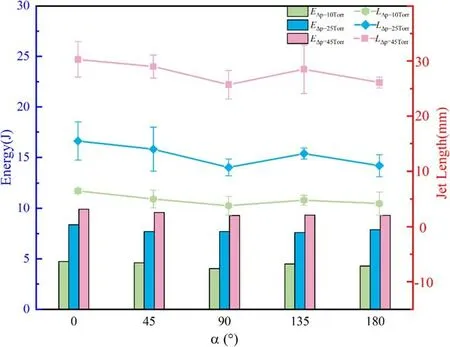
Figure 18.Influence of α on E and L.
When α is unchanged,EandLincrease with an increase inΔp,which is the same as the conclusion in section 4.2.Ldecreases when α increases from 0° to 90°,andΔpremains unchanged;conversely,when α increases from 90°to 180°,Lfirst increases and then decreases.The law ofEis the same as that ofL.The experimental results show that theLrelationship at different angles isLα=0°>(Lα=45°andLα=135°)>Lα=180°>Lα=90°whenW2=0 l min-1andΔpis unchanged.The lengths ofLα=45°andLα=135°are similar.
The numerical simulation shows that the maximum static pressure on the surface of the igniter shell is at α=0°.At this time,Δpbetween the inlet and outlet of the igniter is the largest;therefore,Lis the largest.
When α increases from 0° to 90°,the static pressure on the surface of the igniter decreases continuously and reaches a minimum when α=90°.In the process of increasing α,the pressure difference between the inlet and outlet of the gliding arc igniter is continuously reduced,resulting in a continuous decrease inL,which reaches its smallest value at α=90°.
When α increases from 90°to 180°,the static pressure on the surface of the igniter shell decreases continuously.The direction of the guide hole is opposite to the flow direction of the airflow in the upper cavity.Compared with the interval α=0°-90°,when the airflow enters the cathode channel,more energy from the airflow is given to the axial velocity.The increase in axial velocity weakens the degree of arc distortion,which is conducive to arc elongation.Therefore,Lα=135°>Lα=180°>Lα=90°.
The three parameters all have great influence onEandL.The optimal discharge and jet effect can be achieved when Δp=45 Torr,α=0°,andW2=0 l min-1under the experimental conditions.EandLwill be deteriorated when the gliding arc conditions deviate fromΔp=45 Torr,α=0°,andW2=0 l min-1.
5.Conclusion
In this study,we simulated the induct and bypass of an afterburner and designed a twin-duct ignition platform that can independently supply air without the two flows interfering with each other.COMSOL software was used to numerically simulate the flow field area during the gliding arc operation and reveal the flow field structure of the igniter.The gliding arc plasma jet igniter driven by the pressure difference was used to study the influence ofΔp,W2,and α onEandL.The main conclusions are as follows:
(1)The numerical simulation results show that the air velocity inside the igniter increases asΔpincreases.As the airflow in the lower cavity increases,the air velocity in the lower cavity increases,and the interference to the airflow from the cathode channel increases.The flow field near the exit of the gliding arc igniter is undisturbed under the protection of the swirl sheath.The protective capacity of the swirl sheath decreases with an increase in the axial displacement of the igniter jet.
(2)The experimental results show three stages in the development of the gliding arc breakdown.The gliding arc igniter is regarded as a capacitor storing energy before the air broken down.During the arc evolution stage,it is divided into three discharge modes,and the voltage and current characteristics in different modes are summarized.The gliding arc is in the B-G mode when it is near the breakdown position.It enters the B-GII mode before the cathode channel is blown out,and it enters the stable A-G mode after the gliding arc is blown out.The arc fracture stage is mainly affected by two factors:instantaneous power and arc stiffness.
(3)AsΔpincreases,the changes inEandLshow an initial increase and finally tend to become saturated.The relationship betweenLandΔpobtained by data fitting isL=3-2.47/(1+(Δp/25)4).EandLincrease by 107.3%and 366.2%,respectively,whenW2=0 l min-1,α=0°,andΔpincreases from 10 to 70 Torr.The main reasons for this phenomenon are as follows:asΔpincreases,the outlet of the cathode channel produces interference flow that affects the continued development of the gliding arc;the lower surface of the lower cavity inhibits the flow of the airflow ejected from the cathode channel.
(4)IfΔpand α are unchanged,bothEandLdecrease whenW2is increased,while the discharge effect worsens.The proportion of the decrease inEandLdecreases whenΔpincreases.EandLdecrease by 18.2% and 37.3%,respectively,and the gliding arc offset angle is increased by 8.9°whenΔp=45 Torr andW2is increased from 0 to 250 l min-1.
(5)The influence of different installation angles onLandEis analyzed.The relationship ofLisLα=0°>(Lα=45°andLα=135°)>Lα=180°>Lα=90°whenW2=0 l min-1and Δpare unchanged.When α increases,the static pressure value on the surface of the igniter decreases continuously.When α>90°,the airflow energy in the cathode channel is more distributed to the axial velocity,causingLto increase.
Acknowledgments
We would like to acknowledge the support and contributions from the rest of the faculties in the laboratory.This work was supported by National Science and Technology Major Project(No.2017-III-0007-0033).
 Plasma Science and Technology2022年11期
- Plasma Science and Technology的其它文章
- Interaction of an unwetted liquid Li-based capillary porous system with high-density plasma
- Nanosecond laser preheating effect on ablation morphology and plasma emission in collinear dual-pulse laser-induced breakdown spectroscopy
- Understanding the changing mechanism of arc characteristics in ultrasound-magnetic field coaxial hybrid gas tungsten arc welding
- An equivalent model of discharge instability in the discharge chamber of Kaufman ion thruster
- Comparative study of pulsed breakdown processes and mechanisms in self-triggered four-electrode pre-ionized switches
- Investigation of stimulated growth effect using pulsed cold atmospheric plasma treatment on Ganoderma lucidum