
Propulsion Performance of Spanwise Flexible Wing Using Unsteady Panel Method
2020-09-29 00:53:08NAJAFISaeedandLIUPengfei
NAJAFI Saeed, and LIU Pengfei
Propulsion Performance of Spanwise Flexible Wing Using Unsteady Panel Method
NAJAFI Saeed1), *, and LIU Pengfei2)
1) Ocean Engineering and Technology Department, Iranian National Institute for Oceanography (INIO), Tehran 1411813389, Iran 2) Marine, Offshore and Subsea Technology, School of Engineering, Newcastle University, Newcastle upon Tyne, NE1 7RU, UK
In this paper, the propulsion performance of a spanwise flexible oscillating wing, which is broadly similar to the undulation of a fin fluke, is investigated. The geometry of the fluke underwent three prescribed harmonic oscillating motions simultaneously while surging with constant velocity. The effect of deflection phase angle, flexibility parameter, and wing tip deflection amplitude on thrust coefficient and swimming efficiency was studied. A low-order unsteady panel method coupled with a time stepping algorithm for free wake alignment is implemented in a computer program to estimate the propulsion efficiency of lifting bodies. A novel approach is introduced to evaluate the singular integrals of line vortices by using an adaptive mollifier function. This method is an efficient way to accelerate computational speed by reducing the order of problem from R3to body boundaries. Results present the significant effect of phase angle on the propulsion characteristics of oscillating fluke.
propulsion performance; fin whale fluke; flexible wing; panel method; wake alignment
1 Introduction
Fish locomotion in body caudal fin swimmers is mostly supplied by large-amplitude lateral undulations of the one-third posterior part of the body. Harmonic oscillations of caudal fin have a significant effect on propulsion performance. The kinematic parameters of these harmonic motionsare set naturally such that optimized efficiency is achieved by the animal. In case of improper combination of motion parameters, adverse pressure distribution on the body and loss of performance would occur. Vorticity control is a key factor in achieving high propulsive performance. The order of magnitude of hydrodynamic forces is directly related to the pattern of vortex shedding from the body. Proper adjustment of the kinematic parameters of body motion (amplitude, frequency, and phase angle) would result in an appropriate vorticity control mechanism.
Experimental investigation of the propulsive performance of flexible motion mechanisms is costly because it involves the use of expensive state-of-the-art equipment (, electroactive polymers), which is needed to accurately simulate real motions. Some mesh-based numerical methods such as finite volume and finite element are unsuitable for hydrodynamic simulation of fluid flow around deforming boundaries because of the large computational cost for upgrading the position of grid nodes in each time step. By contrast, panel method based on boundary inte-gral equations (BIE) is convenient for numerical simulation of problems with large deformation boundaries. By using a three-dimensional inviscid, incompressible solver based on BIEs, this research investigates the effect of phase angle, spanwise flexibility, and deflection amplitude of the hydrodynamic performance of spanwise flexible oscillating wing, which is to some extent similar to a fish caudal fin.
One of the earliest models for predicting the propulsion efficiency of oscillating wing was proposed byGarrick (1936). He developed a linear analytical solution for incompressible potential flow over flat-plate airfoil. Performance was overpredicted using this approach.
A numerical simulation of flexible wing was presented by Liu and Bose (1997). They used a time-domain low-order panel method to compute the propulsion performance of a spanwise fin whale fluke. This method has been applied to estimate the effect of variations in the magnitude and phase angles of the spanwise flexibilities of a three-dimensional wing. They showed that increasing the magnitude of spanwise deflection in small phase angles (±35?) reduced the propulsion performance of locomotion compared with rigid oscillations. However, at large phase angles (±180?) at a relatively small deflection, efficiency and thrust were substantially increased.
Heathcote(2008) set up an experiment in a water tunnel to investigate the effect of spanwise flexibility on the hydrodynamic performance of rectangular oscillating foil. Nondimensional thrust, power coefficient, and propulsion performance were examined. They observed that at Strouhal numbers greater than 0.2, a small increase in thrust coefficient yielded higher propulsion efficiency for a moderate flexible wing. However, a high degree of flexibility deteriorates the results.
Le(2010) investigated the effect of chord flexibility on the aerodynamic performance of a flapping wing by using a grid deformation technique coupled with Navier-Stokes equation to analyze propulsion performance. They observed the maximum thrust achieved at a zero phase angle, and the optimum phase angle depends on the wing oscillation amplitude. As an example of experimental measurements, Hu(2010) investigated the effect of skin flexibility on the propulsion performance of flapping wings through a series of experiments on a nylon wing and latex wing compared with a conventional rigid wing. One observation reveals that the latex wing, which is more flexible than the others, has the best propulsion performance during flapping motion. Aono(2010) presented a combined approach that included experimental and computational methods to investigate the effect of aero-elasticity coupled with aerodynamic characteristics of flapping wing on propulsion performance. They realized the interaction of leading and trailing vortex can drastically improve thrust generation performance. Their numerical results were verified by their observations. Kang(2011) investigated the effect of chordwise, spanwise, and isotropic flexibility on thrust generation and propulsion performance of flapping wings. They observed that optimum performance was achieved when the flapping frequency was almost half the natural frequency. Fish(2014) measured the propulsive forces produced by a swimming dolphin by using bubble DPIV method. A jet flow that included strong vortices due to the oscillations of the flukes was generated in the wake of the dolphin. The thrust was calculated by using Kutta-Joukowski theorem on the basis of the measured circulation around shed vortices. The results demonstrated that this method can be used effectively to predict the propulsion performance of fish.Esfahani(2013) investigated the effect of caudal length on propulsion performance of oscillating foils. They defined the kinematics of model based on pitching foil, pitching caudal motion which is closely similar to the real locomotion of fish. To verify their results, they used a computational model based on Theodorsen’s theory and showed that this model can properly estimate the hydrodynamic performance of flapping foil in different Strouhal numbers.
Thaweewat(2018) investigated the propulsion performance of semi-active flapping foil, whose motion is a combination of active heave oscillation with passive pitch controlled by a torsion spring. The effect of flapping frequency and stiffness of torsional spring was investigated using a potential flow solver in conjunction with the Newton-Euler method to determine the position and velocity of flapping foil. This motion is nearly similar to the kinematics of self-pitching propellers in marine application. Findings indicate efficient performance in a wide range of Strouhal numbers.
The propulsion performance of semi-active flapping foils was also investigated byZhan(2017). They used a numerical model of NACA0015 undergoing a prescribed pitch motion coupled with free heaving movements, whose oscillations were controlled by a linear spring, in an unsteady gusty flow and used the commercial software FLUENT. They showed that when the phase difference between gust flow and pitch motion is 180?, the maximum power could be achieved by the mechanism.
Esfahani(2015a, b) and Karbasian and Esfahani (2017) proposed a novel mechanism inspired by fish swim- ming pattern to increase the propulsion performance of flapping foil. They also numerically examined their proposed model, which is a combination of periodically horizontal and vertical movements of foil, at a low Reynolds number (4×10⁴) and observed that this model could partially enhance the propulsion performance under certain circumstances.
Pourmostafa and Ghadimi (2018) investigated the propulsion efficiency and thrust coefficient of a flapping foil in tandem arrangement with a stationary wing with a constant angle of attack (AOA) by using a low-order boundary element formulation. The effect of AoA and distance between wings was examined through a series of systematic simulation. Results show that the maximum power would be attained when the AOA of the aft wing (stator) is near zero. In addition, the interaction of vortex structure of two wings was studied.
As stated above, many numerical inviscid models for the propulsion performance of flexible wing were developed. Generally, all of them overestimate the propulsion efficiency because of their key limitation in modeling leading-edge vortex shedding. The absence of leading-edge vortices and its effect on surface pressures would lead to overestimation of thrust coefficient and underestimation of input power. Therefore, these models overestimate the locomotion efficiency, which is defined the ratio of thrust coefficient to input power coefficient.
The selection of a numerical model is a compromise between accuracy and computational cost. For problems in which pressure forces are dominant rather than viscous, inviscid methods are a good choice. Given the higher computational speed of the panel method in comparison with Navier-Stokes models, this study uses a low-order panel method coupled with an unsteady wake alignment algorithm and implemented into a computer program to estimate the propulsion efficiency of rigid and flexible lifting bodies. To verify the results, the hydrodynamic coefficients of a rectangular flexible wing, which was previously studied by Heathcote(2004, 2008), Young and Lai (2004) and Young (2005), were examined. The results present good agreement between experimental measurements and panel method in the moderately loaded condition (reduced frequency greater than 1).
2 Materials and Methods
Consider a general flexible body denoted bySundergoing prescribed translating and angular motions and spanwise undulations about its centerline with sharp trailing edges, as shown in Fig.1. An infinitesimal thin vortex wake (S=SUS) is shed from the sharp trailing edges continuously as time proceeds. In our terminology, the wake sheet is composed of two types of panels, the panels adjacent to the railing edge are denoted byS(colored with red in Fig.1) and known as Kutta strip, and the remaining panels on the wake sheet denoted withS(colored with gray) are known as free shear layer. The fluid is assumed inviscid, irrotational, and incompressible except on the wake sheet, allowing the existence of a velocity potential(,) for any pointwithin the fluid, which satisfies Laplace’s equation. This assumption is valid for the problems where the vorticity and boundary layer effects are not important. In other words, for the outer flow region of airfoils where the magnitude of velocity gradients is negligible and in pressure-dominant problems with weak effects of shear flow, potential flow assumption is a proper, affordable approach.

Two coordinate systems were considered in our study: an inertial global coordinate system, which is fixed in space, and a local coordinate system, which is instantaneously fixed on the flexible body. The mean periodic undulations of the body are prescribed with reference to, and the global translational motion of the body is described with respect to.
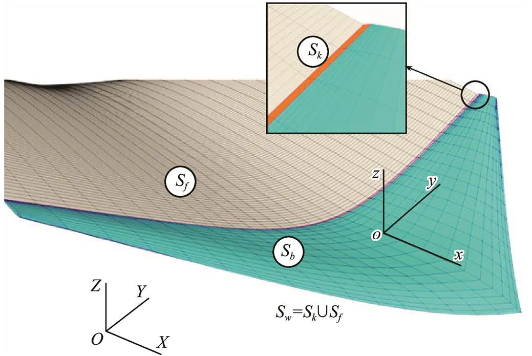
Fig.1 Schematic representation of the problem; OXYZ is the global reference system while oxyz is body fixed.
In the boundary element formulation, perturbation velocity potential can be found using a distribution of fundamental solutions (source, doublet, vortex,) on the body with smoothly varying strengths. To calculate the velocity potential of each panel, a BIE made up of a linear combination of point singularities should be solved as follows:
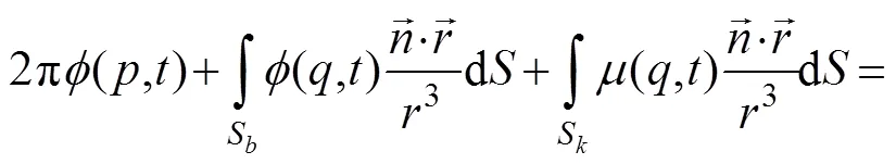

As shown in Eq. (1), we use point sources and doublets on the body and point doublets over the wake surface. At each time step, the strength of singularities on free shear layerSis determined by the previous flow field information. The unknown strength of the Kutta stripSthat is shed from the trailing edge with time is addressed through the unsteady Kutta condition, which is applied to the sharp trailing edges of the body to enforce smooth flow leaving the body (no pressure jump at trailing edges). At any time, the strength of the Kutta strip velocity potential equals the jump in the body perturbation potential between the upper and lower surfaces near the trailing edge.
Any pressure jump between upper and lower panels of trailing edge will cause instability in fluid flow. To avoid this condition, two types of Kutta condition can be applied at the trailing edge to close the system of BIEs: a linear Morino type (Morino and Kuo, 1974) and a nonlinear pressure type, which was first introduced by Lee (1987). They have the same accuracy for simple geometries with orthogonal panels in low-frequency motions. However, for complex grids, such as high skew propellers with highly varying pitch distribution from root to tip, or in high-frequency oscillating motions, linear Morino type is likely to diverge due to infinite induced velocity caused by pressure jump at the trailing edge. In terms of computational time, the nonlinear pressure condition must be solved in an iterative manner using nonlinear methods such as Newton-Raphson. This approach takes much more time, yet it guarantees continuous pressure distribution near the trailing edge. In this study, minimal difference was found between the methods, and the former method was selected. On the basis of the linear Morino type Kutta condition, one can write the doublet intensity of wake panel adjacent to the trailing edge (third term in LHS of Eq. (1)) as follows:
Thus, at each time step, writing Eq. (1) for all body panels will construct a system of equations, and body perturbation velocity potentials would be computed along with simultaneous solving of this system.
To find the new position of the wake sheet iteratively in time, the mean induced velocity of collocation nodes on free shear layer should be computed. It can be calculated by taking the gradient from Eq. (1) as follows:
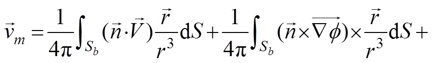

Knowing the induced perturbation velocities at each grid pointx(=1, ···,), wheredenotes the number of nodes representing the free wake of each lifting surface at each time step, the new position of the nodes can be calculated using a first-order approximation such as

where dis the size of the time step and affected by the stability criteria of the problem. Given the singular nature of boundary integral equations (3in denominator of integrands), the most crucial part of the numerical simulation deals with the treatment of singular integrals to control the stability of the problem. The strength of singularity is relative to the position of control point toward the integration point. In general, we encounter two types of singularities (Najafi and Abbaspour, 2017):
1) Weakly singular integrals appearing in the calculation of self-influence coefficients of dipoles (second and third terms in LHS and second term in RHS of Eq. (1)) and self-influence coefficients of the source term (first term in RHS of Eq. (1)). Delhommeau (1989) developed an analytical expression based on the multipole expansion by Hess and Smith (1962) to estimate these integrals. In the present study, the analytical relations of Delhommeau were implemented in the algorithm.
2) Hypersingular integrals or non-integrables appear in the third and fourth terms of Eq. (3). These integrals are similar to the famous Biot-Savart line integrals in electromagnetics and can be calculated analytically as follows (Politis, 2016):
To calculate the integrals of Eq. (3), we decompose each panel into a number of vortex lines that compose the edges of the panel. Therefore, in case of a quadrilateral panel, the contribution of four vortex filaments should be computed separately. Induced velocity of the panel would be the vector summation of the induced velocity by each filament.
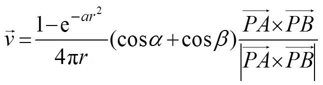
Now, suppose that a vortex filament with unit strength exists from point A to B in R3(Fig.2). The induced velocity of this line vortex in point P can be calculated as

whereis the normal distance from point P to the vortex line, andandare the angles between the line connecting the control point to the ends of the vortex filament. However, in case P moves closely toward the vortex line (→0), the induced velocity approaches infinity.

The implementation of a constant mollifier coefficientin this expression cannot properly capture the reality of vortex shedding. Increasing this coefficient will reduce the cutoff radius and lead to a decrease in the damping intensity of the mollifier, thereby resulting in an unstable numerical solution. In Fig.3a, the wake rollup pattern is simulated for an airfoil with a non-zero AOA and in burst starting motion. The implementation of a high value mollifier leads to vortex wake instabilities, especially in the old wake stripes that are stronger than the new ones. The selection of lower values results in more stability, but as shown in Fig.3b, it may suppress the rollup pattern of the wake sheet. In general, selecting a proper value for mollifier parameters depends on the size of vortices, the physicaldimension of the geometry, and the time step of the simulation. The question now is what method is needed to properly capture all vortex wakes that have different strengths.
In this study, we implement a novel approach by using an adaptive multiplier to control the instabilities of the wake sheet that arise from singular integrals of vortex filaments. The magnitude of this multiplier is a function of vortex strength and a good criterion for the strength of a vortex can be its age. Hence, the mollifier function could be expressed as follows:
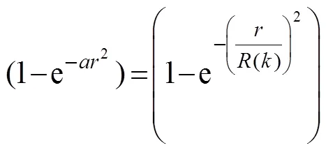
In this relation,(), is an effective cutoff radius that is determined based on ‘’, the number of wake stripes. The result of the implementation of this approach on the wake rollup pattern of a lifting wing with NACA0012 profile and aspect ratio 6 at 10? AOA is shown in Fig.3c. The vortex wake rollup was preserved, and instabilities were properly controlled.
In this case, the convergence of the lift coefficientthe length of the vortex wake is shown in Fig.4.
The next step is the calculation of forces and moments by integrating the pressure distribution on the body. The surface gradient of velocity potentials on body panels needs to be taken to calculate the pressure distribution by using unsteady Bernoulli equation. We have
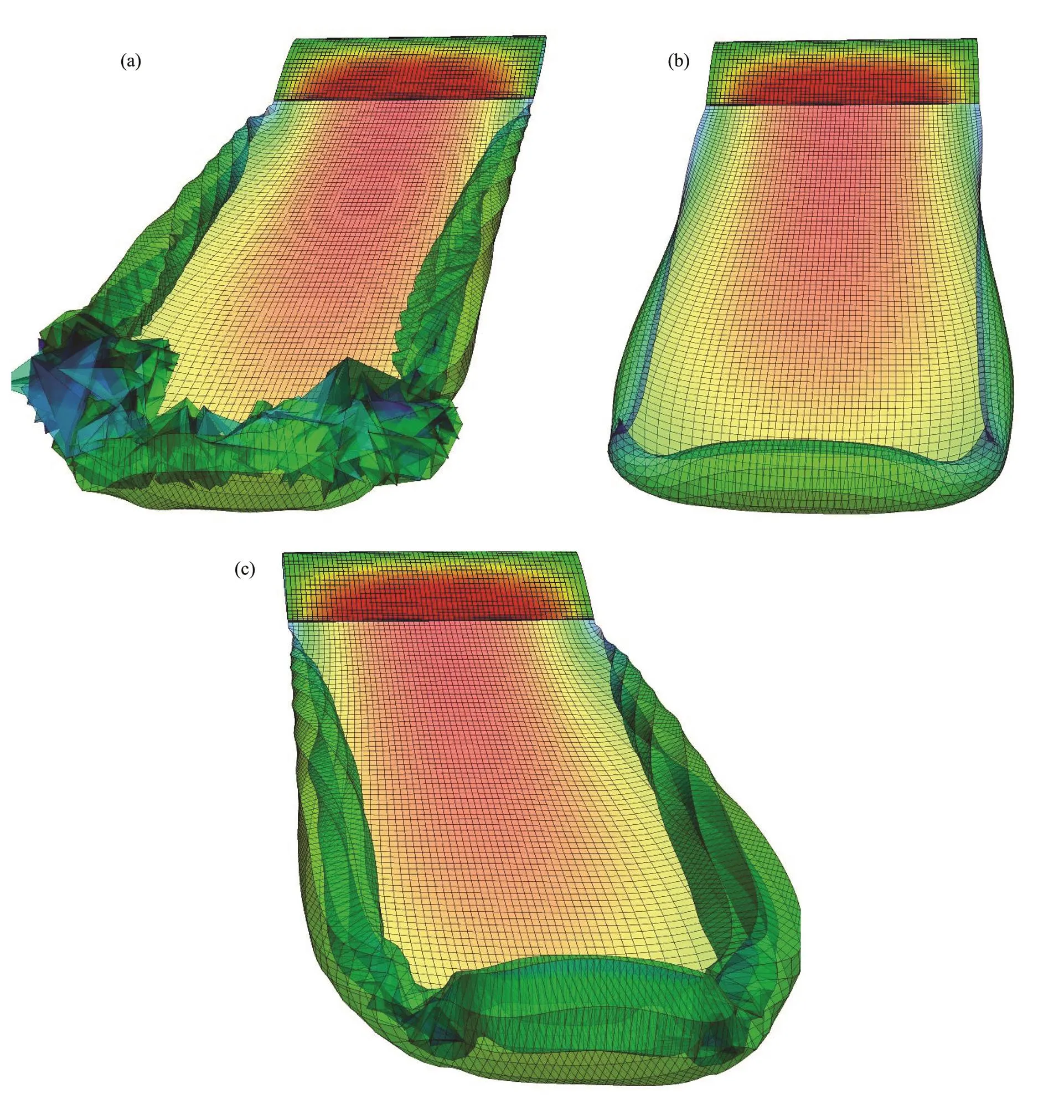
Fig.3 Effect of different factors in the intensity of damping multiplier. (a) constant high coefficient (weak filter), (b) constant low coefficient (strong filter), (c) adaptive filtering.
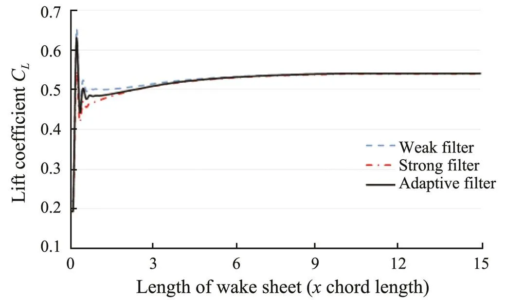
Fig.4 Time history of lift coefficient versus length of wake sheet for lifting wing.
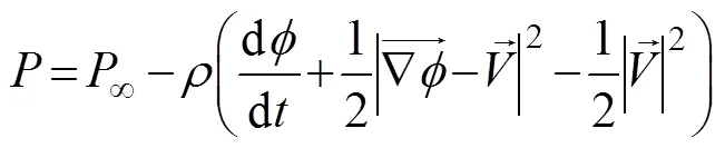
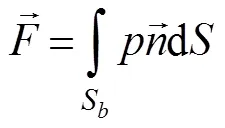
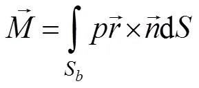
whereis the fluid density. Then, the hydrodynamic forces and moments can be estimated as follows:


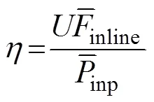
Finally, we define the propulsion efficiencyas


3 Results and Discussion
3.1 Case a: Rectangular Wing
To validate our numerical model, we estimate the propulsion performance of a spanwise flexible wing, which was previously simulated by Young (2005) by using Navier-Stokes equations and also byHeathcote(2008) by using particle image velocimetry (PIV) measurements in a water tunnel. This wing has a NACA0012 cross section, 100mm chord, and 300mm span, and the root undergoes a plunging motion with a nondimensional amplitude of (/=0.175). The geometry of the problem is shown in Fig.5.

Fig.5 Schematic of the problem.
The magnitude of upstream flow velocity is set such that the Reynolds number (=0/) is equal to 30000 and the frequency of root motions is in the range where the Garrick reduced frequency (K=π/0) varies from 0.1 to 4.7. On the basis of the experimental measurements of Heathcoat(2008), due to the flexibility of the wing, the tip follows the movements of the root with a greater amplitude,, inK=1.82, the tip-to-root amplitude ratio was (tip/root=1.76) with a ?117? phase lag relative to the root motion.
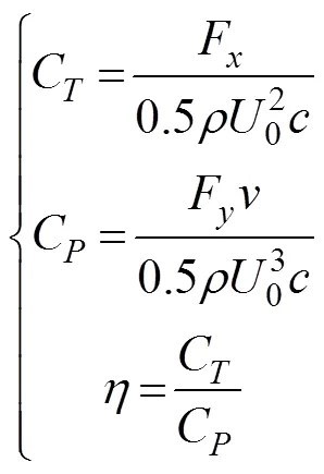
Thrust and power coefficients and propulsion efficiency can be estimated using the following relations:
Prior to the prediction of propulsion efficiency, to evaluate the numerical performance of the present method, the results are given for different grid densities, and the size of the time step and the convergence of the solution are investigated.
As previously stated, an advantage of the present method over the traditional panel method is that grid generation is limited to the body geometry because the free wake sheet paneling is produced during the simulation. Generally, for a wing section, two physical directions along the chord and span of the wing can be defined. Different schemes, including equally or cosine spacing for both directions, can be selected. Cosine spacing is better because more node distribution is found near the leading-edge and wing tips, where the geometry changes abruptly. Cosine spacing also mollifies the numerical instabilities during runtime.
To show the independence of numerical results with the number of panels, four different geometries with 24×16, 32×24, 40×32, and 48×40 panel elements, as shown in Fig.6, were created. In this notation, the first and second numbers indicate the number of panels in the chordwise and spanwise directions, respectively, on each side of the wing. All simulations are carried out on a 2.6GHz Intel Core i7 processor in the reduced frequency ofK=1.82 with an equal time step until three cycles are completed.
A summary of the results is depicted in Table 1. The selection of the optimum grid is a compromise between computational time and numerical accuracy. Thus, a cost function is defined based on the sum of the normalized error (in comparison with Heathcote experiment) and normalized CPU time. Therefore, the most efficient grid is the one with the minimum cost function (Fig.7).
On the basis of the results, when the 32×24 grid was replaced with a 24×16 grid, the value of relative error decreased suddenly while the total CPU time increased moderately. With the use of this approach, the minimum value of cost function was obtained in the 40×32 grid; therefore, this panel size is the most efficient for simulation in the present test case. Thus, the modeling of the spanwise flexible wing in the other frequencies was conducted with 40×32 surface paneling.
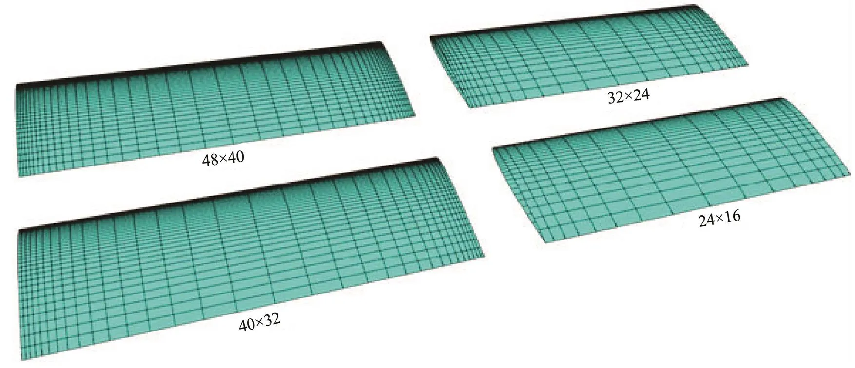
Fig.6 Wing geometry with four different grid densities.
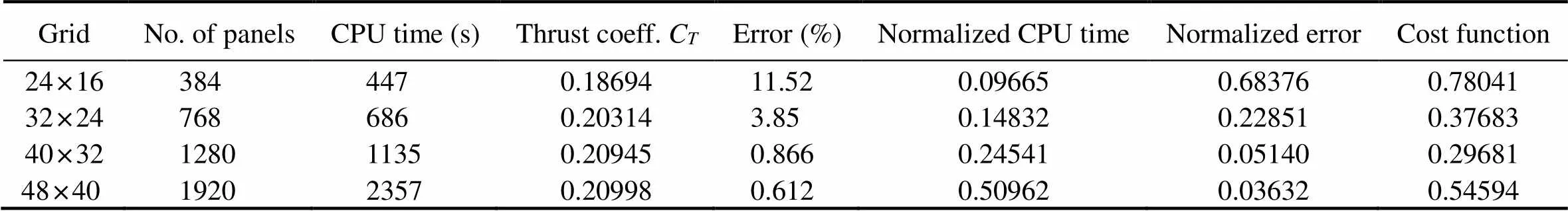
Table 1 Simulation results for different grids
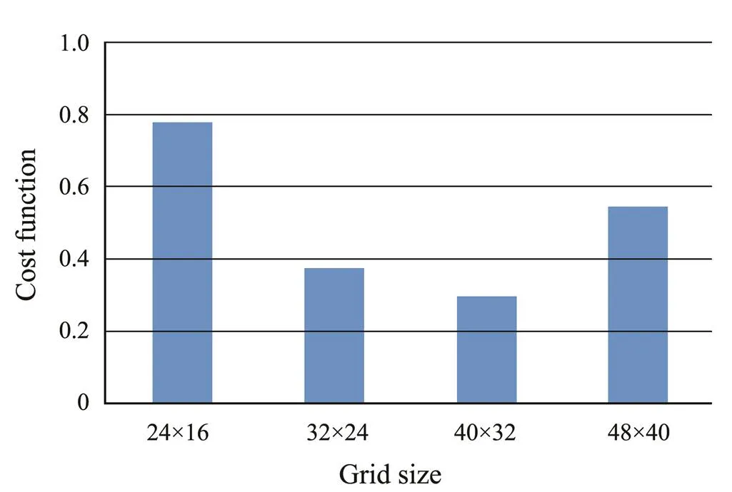
Fig.7 Value of cost function at different grid sizes.
Now we investigate the effect of time step on the convergence of the numerical solution. As previously stated, the position of wake sheet elements is determined during simulation by using a first-order approximation of inducedvelocity of wake nodes. Therefore, the selection of different time steps leads to various sizes of wake elements. Another study was conducted on different values of time step, which determines the length of wake panels, and the time history of lift coefficients can be observed as follows:
To this end, the lifting wing was considered a rigid body with a fixed AOA. Time step value was changed in a series of simulations to control the ratio of wake panel length to wing chord (/) as depicted in Fig.8. The time history of lifting coefficient for different ratios is shown in Fig.9 to ensure the independence of the solution.

Fig.8 Value of cost function at different grid sizes.

Fig.9 Time history of lifting coefficient for different time steps and wake panel lengths.
In the following, the harmonic prescribed motion of the wing is implemented, and the propulsion performance at different reduced frequencies is investigated. The development pattern of the free wake sheet downstream of the wing is depicted at a reduced frequency ofK=1.82. The vortex instabilities that arises from singular integrals, are controlled with an adaptive mollifier function which previously described.
To determine the hydrodynamic parameters, the time average of inline force (F) and normal force (F) was computed. The propulsion performance of the flexible wing when a set of simulations is run at different reduced frequencies is plotted in Fig.11.
Our results were compared with the linear thin airfoil theory of Garrick (1936) by using potential flow assump- tion and Navier-Stokes simulations conducted by Young (2005) and the experimental measurements of Heathcote(2008). As shown in the figures, the present method made better predictions at a vast range of frequencies than more computationally expensive methods such as RANS equations and PIV measurements. In the next step, we simulate the main case.

Fig.10 Wake sheet alignment of the flexible wing. Contours show the strength of potential singularity distribution on body and wake surface.

Fig.11 Performance of rectangular wing.
3.2 Case b: Whale Fluke
The geometry of the fluke was described by Bose and Lien (1989) and Bose(1990) (Fig.12). The main parameters were assumed as follows:
1) Section profile: NACA0012
2) Total span (S): 3.0m
3) Root chord (Cr): 0.87m
4) Wing aspect ratio (=2/, whereis total area of the fluke): 6.1
The total span of the wing was divided into 32 equally spaced grids, while the number of chordwise segments is 16 for the back and the face of the fluke with a cosine spacing.
We suppose the fluke is undergoing four separate motions: surging with constant velocity () in the-direction, harmonic heave motion in the-direction with amplitude (0=C), harmonic pitch motion about the trailing edge of the wing (-axis) with amplitude (0=20?), and harmonic spanwise deflection similar to a cantilever beam with the-plane as the plane of symmetry. No chordwise deflection is used in this simulation, and all oscillations are carried out with the same frequency () and different phase angles. The equation of spanwise deflection is as follows:
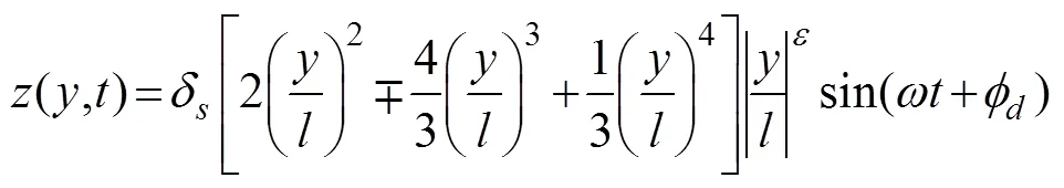
where=/2 is the length of half-span,δis the maximum deflection at the tip of the fluke and stated as a percentage of half-span,is the flexibility parameter, andis the deflection phase angle. The effect of flexibility parameter in the spanwise deflection of the fluke is depicted in Fig.13. A high value ofcorresponds to an increase in the rigid length of the wing.

Through a sensitivity analysis on the effective parameters of spanwise deflection on propulsion performance of fin whale fluke, a set of simulations was conducted as Table 2.
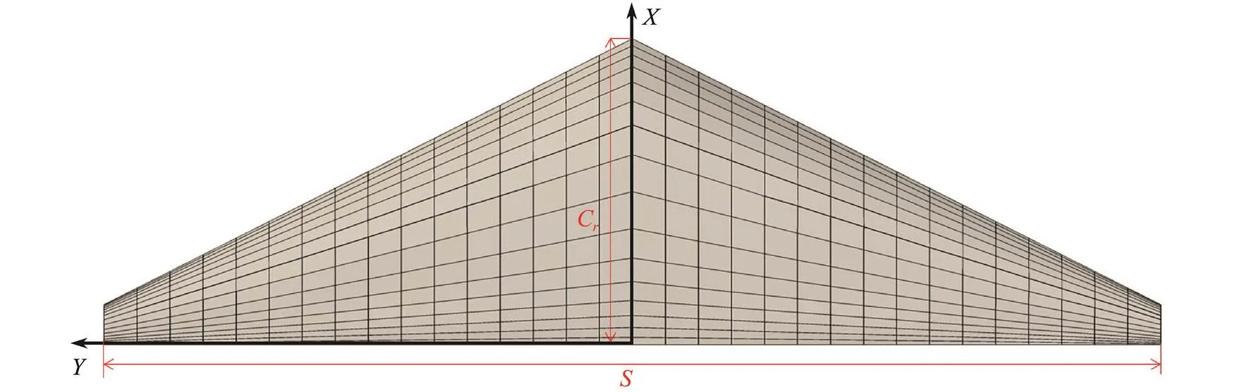
Fig.12 Geometry of fin whale fluke.
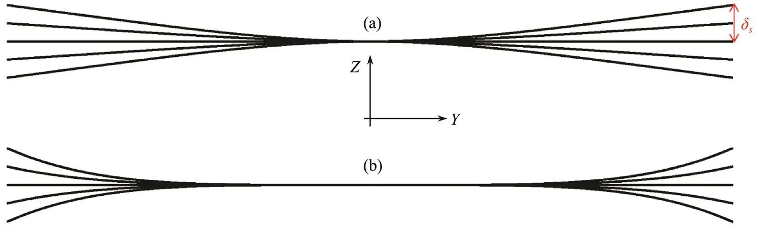
Fig.13 Effect of flexibility parameter in spanwise deflection of fluke. (a) ε=0, (b) ε=3.

Table 2 Range of effective parameters for simulation
The frequency of oscillationfor all harmonic motions is 0.2π (rads?1). The phase angle of heave and pitch motion are assumed π/2 and π respectively. The surging velocityin all cases is 0.87 (ms?1). The trajectory of the fin whale fluke, which is combination of three simultaneous motion, during one period is shown in Fig.14.

Fig.14 Trajectory of fin whale fluke in one period.
3.3 Effect of Phase Angle (fd)
As mentioned before (Table 2), in the first case study, we investigate the effect of deflection phase angle on the propulsion characteristic of whale fluke. Propulsion efficiency could be estimated based on Eq. (12), and the thrust coefficient formula is stated as follows:

In this set of simulations, flexibility coefficient () and deflection amplitude (δ) are considered 0 and 10% of the half-span, respectively. Each period is divided into 50 steps. Therefore, the size of each time step is 0.2s.
Figs.15 and 16 show a comparison between spanwise flexible wing at different phase angles with a rigid one. The phase angle of harmonic deflections is under consideration; thus, a change in the phase angle has no effect on the characteristics of rigid oscillations. One point that can be understood from these figures is that the propulsion efficiency of rigid oscillations is almost an average of flexible movements with different phase angles. On the basis of Fig.15, the spanwise flexible oscillation of the fluke is more efficient than rigid oscillations only in a specific range of phase angles from [?140?, +20?]. This finding is consistent with Liu’s research (Liu, 1996), which states that the passive-mode phase angle is between [?35?, 0?]. The maximum efficiency in the case of spanwise flexible oscillations is 69.7% at a phase angle of ?60?, while the minimum efficiency is 61.6% at a phase angle of +120?. Therefore, spanwise flexibility with a random phase angle may either improve or impair the efficiency up to 4% relative to the rigid oscillating wing. Three significant phase angles, namely, ?60?, 0?, and +120?, where the optimum efficiency was found, were chosen to investigate the effect of other parameters on propulsion performance.
A comparison of Fig.16 and Fig.15 shows that the thrust coefficient has an approximately 150? phase priority relative to propulsion efficiency. This finding means that the efficiency curve has a hump in phase angle, in which the thrust coefficient became hollow. Similar to the efficiency curve, the thrust coefficient of rigid oscillating wing is the average of spanwise flexible fluke with different phase angles. Extremums take place at phase angles ?90? and +90? with a ±14% deviation relative to average.

Fig.15 Comparison of propulsion efficiency of spanwise flexible fluke at different phase angles with a rigid oscillating wing.
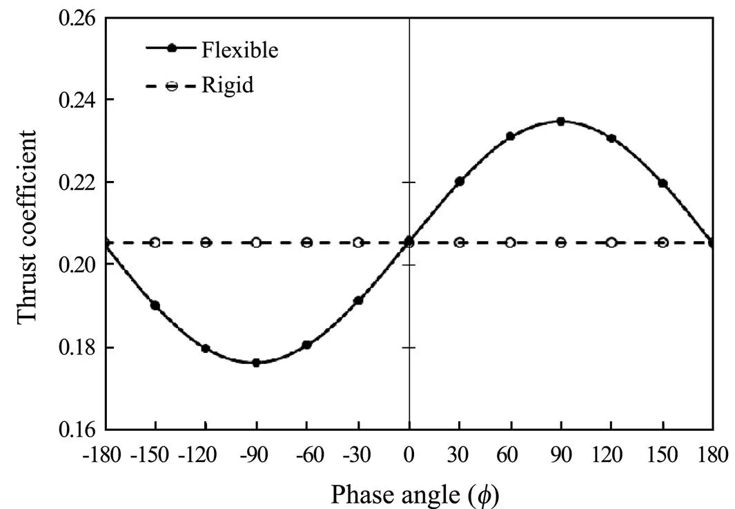
Fig.16 Comparison of thrust coefficient of spanwise flex- ible fluke at different phase angles with a rigid oscillating wing.
The wake rollup pattern of oscillating fluke in accordance with case 1 (Table 2) and=?60? after different time steps is shown in Fig.17.

Fig.17 Wake rollup pattern of spanwise flexible fluke at fd =?60?.
The major hydrodynamic forces generated by whale flukes during swimming are thrust in the-direction and lifted in the-direction. The time history of the dimensionless form of these forces during the three periods is shown in Fig.18. On the basis of the rules of vortex Karman street, the frequency of inline force (thrust) is twice the frequency of the lift generated by the wing.
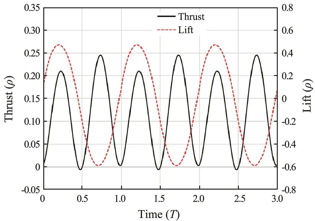
Fig.18 Time history of dimensionless form of lift and thrust.
3.4 Effect of Flexibility Parameter (ε)
In this section, the effect of flexibility parameter on propulsion characteristic of whale fluke was investigated. As mentioned before, analysis was conducted at phase angles of ?60?, 0?, and +120?, which are the extremums of the efficiency curve. At these phase angles, we increase the rigid length of the wing by changing flexibility parameter (), while the maximum deflection at wing tip is kept fixed as 10% of the half-span (δ=0.1) on the basis of case 2 in Table 2. Fig.19 and Fig.20 show the trend of propulsion efficiency and thrust coefficientat different phase angles, respectively.
On the basis of these charts, increasing the rigid length of the fluke improved the efficiency of oscillations at phase angle (=120?) but impaired it at (=?60?). One important outcome of the results is that a fully flexible fluke (,=0) in combination with (=?60?) is the most efficient point. A detail that should be noted is that the uncontrolled increase of () may ruin the stability of the problem due to the large gradient of wing deflection near the tip.

Fig.19 Propulsion efficiency of variable flexible length fluke at different phase angles.

Fig.20 Thrust coefficient of variable flexible length fluke at different phase angles.
3.5 Effect of Deflection Amplitude (δs)
In the last case study, we investigate the effect of tip fluke deflection on the propulsion performance of spanwise flexible oscillating wing. On the basis of case 3 in Table 2, deflection amplitude (δ) increased from zero (rigid wing) until 30% of the half-span () with 5% increments. A large deflection amplitude magnifies the non- linearity effects and may outshine the results.
To model a fully flexible wing, the rigid length of the fluke was set to zero in all simulations (=0). The following figures show the propulsion performance of the wing for the different phase angles. An interesting result similar to the previous case study was observed. As shown in Fig.21 and Fig.22, at phase angle (=120?), increasing the tip deflection amplitude up to 30% of the half-span will reduce the propulsion efficiency by up to 12%. However, at phase angle (=?60?), doing so will increase the efficiency by up to 8%. This result indicates the role of phase angle in the propulsion performance of harmonic oscil- lating wings.
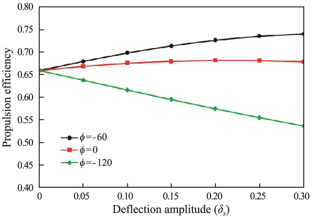
Fig.21 Propulsion efficiency of fluke at different phase angles and deflection amplitude.
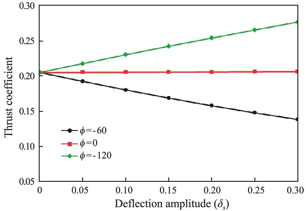
Fig.22 Thrust coefficient of fluke at different phase angles and deflection amplitude.
These figures show that changing the deflection amplitude has no significant effect on propulsion performance at phase angles near (=0?).
4 Conclusions
A computer program based on boundary element formulation, including an unsteady wake alignment model, was generated to estimate the propulsion performance of rigid and flexible bodies. The most important advantage of these tools is that they decrease the order of the problem from R3space to body boundaries, which is divided into surface panels. As a result of the inherent instability of boundary element formulation that originates from singular integrals, a smoothing function to damp the effect of singularities is imposed on the solution. This mollifier controls the stability of the model by applying a multiplier exponential function to hypersingular integrals.
The hydrodynamic performance of a flexible rectangular wing that was experimentally and numerically simulated was examined to validate our model. Then, the propulsion performance of a spanwise flexible wing, which is to some extent similar to a fin whale fluke, was investigated. The geometry of the fluke underwent three harmonic oscillations simultaneously while surging with constant velocity. The effect of deflection phase angle, flexibility parameter, and wing tip deflection amplitude on the thrust coefficient and swimming efficiency was studied. The results show that the highest efficiency was achieved when the phase angle of harmonic deflections () was ?60? while the flexibility parameter of the wing was set to zero (full-length flexible mode). This condition was improved by increasing the deflection amplitude of the tip. The worst case was preceded by 180?from this point at (=120?). Nevertheless, increasing the deflection amplitude deteriorates this situation.
Acknowledgement
The work described in this paper has been carried out during a research opportunity. I would like to thank the Iranian National Institute for Oceanography (INIO), Ocean Engineering and Technology Department for this opportunity they gave me.
Aono, H., Chimakurthi, S. K., Wu, P., S?llstr?m, E., Stanford, B. K., Cesnik, C. E., Ifju, P., Ukeiley, L., and Shyy, W., 2010. A computational and experimental study of flexible flapping wing aerodynamics.. Orlando, Florida, AIAA-2010-554.
Bose, N., and Lien, J., 1989. Propulsion of a fin whale (): Why the fin whale is a fast swimmer., 237 (1287): 175-200.
Bose, N., Lien, J., and Ahia, J., 1990. Measurements of the bodies and flukes of several cetacean species., 242 (1305): 163-173.
Delhommeau, G., 1989. Amélioration des performances des codes de calcul de diffraction-radiation au premier ordre.. Nantes, France, 69-88.
Esfahani, J., Barati, E., and Karbasian, H. R., 2013. Effect of caudal on hydrodynamic performance of flapping foil in fish-like swimming., 42: 32-42.
Esfahani, J., Barati, E., and Karbasian, H. R., 2015a. Fluid structures of flapping airfoil with elliptical motion trajectory., 108: 142-155.
Esfahani, J., Karbasian, H. R., and Barati, E., 2015b. Proposed kinematic model for fish-like swimming with two pitch motions., 104: 319-328.
Fish, F. E., Legac, P., Williams, T. M., and Wei, T., 2014. Measurement of hydrodynamic force generation by swimming dolphins using bubble DPIV., 217 (2): 252-260.
Garrick, I. E., 1936. Propulsion of a flapping and oscillating airfoil. National Advisory Committee for Aeronautics, Report No. 567, 9pp.
Heathcote, S., Martin, D., and Gursul, I., 2004. Flexible flapping airfoil propulsion at zero free stream velocity., 42 (11): 2196-2204.
Heathcote, S., Wang, Z., and Gursul, I., 2008. Effect of spanwise flexibility on flapping wing propulsion., 24 (2): 183-199.
Hess, J. L., 1972. Calculation of potential flow around arbitrary three dimensional lifting bodies. McDonnell Douglas Corporation, Report No. MDCJ 5679-01.
Hess, J. L., and Smith, A. M. O., 1962. Calculation of non-liftingpotential flow about arbitrary 3D bodies. Douglas Aircraft Division, Report No. E.S. 40622, California, 177pp.
Hu, H., Kumar, A. G., Abate, G., and Albertani, R., 2010. An experimental investigation on the aerodynamic performances of flexible membrane wings in flapping flight., 14 (8): 575-586.
Kang, C.-K., Aono, H., Cesnik, C. E., and Shyy, W., 2011. Effects of flexibility on the aerodynamic performance of flapping wings., 689: 32-74.
Karbasian, H. R., and Esfahani, J., 2017. Enhancement of propulsive performance of flapping foil by fish-like motion pattern., 156: 305-316.
Le, T. Q., Ko, J. H., Byun, D., Park, S. H., and Park, H. C., 2010. Effect of chord flexure on aerodynamic performance of a flapping wing., 7 (1): 87-94.
Lee, J., 1987. A potential based panel method for the analysis of marine propellers in steady flow. PhD thesis. Massachusetts Institute of Technology.
Liu, P., 1996. A time-domain panel method for oscillating propulsors with both chordwise and spanwise flexibility. PhD thesis. Memorial University of Newfoundland.
Liu, P., and Bose, N., 1997. Propulsive performance from oscillating propulsors with spanwise flexibility., 453: 1763-1770.
Morino, L., and Kuo, C.-C., 1974. Subsonic potential aerodynamics for complex configurations: A general theory., 12 (2): 191-197.
Najafi, S., and Abbaspour, M., 2017. Numerical study of propulsion performance in swimming fish using boundary element method., 39 (2): 443-455.
Politis, G. K., 2016. Unsteady wake rollup modeling using a mollifier based filtering technique., 5: 1-28.
Pourmostafa, M., and Ghadimi, P., 2018. Investigating the interaction of two oscillating foils in tandem arrangement, using 3D unsteady boundary element method., 40 (9): 412.
Thaweewat, N., Phoemsapthawee, S., and Juntasaro, V., 2018. Semi-active flapping foil for marine propulsion., 147: 556-564.
Young, J., 2005. Numerical simulation of the unsteady aerodynamics of flapping airfoils. PhD thesis. University of New South Wales.
Young, J., and Lai, J. C. S., 2004. Oscillation frequency and amplitude effects on the wake of a plunging airfoil.,42 (10): 2042-2052.
Zhan, J., Xu, B., Wu, J., and Wu, J., 2017. Power extraction performance of a semi-activated flapping foil in gusty flow., 14 (1): 99-110.
. E-mail: najafi82@gmail.com
April 26, 2019;
January 3, 2020;
March 24, 2020
(Edited by Xie Jun)
 Journal of Ocean University of China2020年3期
- Journal of Ocean University of China的其它文章
- Estimation of the Reflection of Internal Tides on a Slope
- The New Minimum of Sea Ice Concentration in the Central Arctic in 2016
- Investigation of the Heat Budget of the Tropical Indian Ocean During Indian Ocean Dipole Events Occurring After ENSO
- Image Dehazing by Incorporating Markov Random Field with Dark Channel Prior
- Biochemical Factors Affecting the Quality of Products and the Technology of Processing Deep-Sea Fish,the Giant Grenadier Albatrossia pectoralis
- Study on Wave Added Resistance of a Deep-V Hybrid Monohull Based on Panel Method